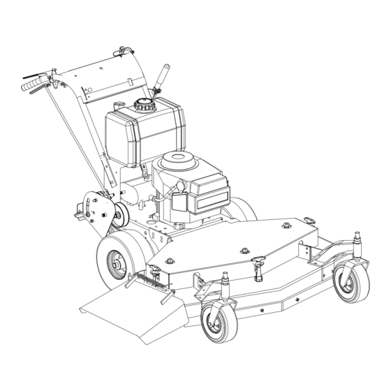
Cub Cadet Commercial G1752 Operator's And Service Manual - Page 11
Browse online or download pdf Operator's And Service Manual for Lawn Mower Cub Cadet Commercial G1752. Cub Cadet Commercial G1752 16 pages. Walk-behind commercial rotary mowers

Figure 6
d. Slip the long blade drive belt off of the pulleys.
e. (48" ONLY) Loosen the idler pull rod which holds
the idler pulley tight against the short blade drive
belt. (Item K, Figure 8.)
f. Remove the short blade drive belt from the pulleys.
g. Place a new short blade drive belt back on the
pulleys and tighten the idler pull rod to hold the idler
pulley tight against the belt.
h. Place a new long blade drive belt through the belt
guide and loop it around the engine pulley and then
around the two deck pulleys. The belt's back side
should ride on the idler pulley.
i. Replace the cap screw, lock washer and nut in the
idler pulley arm.
j. The idler pulleys should be adjusted so that when
the blade clutch is engaged, a ten-pound pull
between two pulleys deflects either belt about 1/2".
Do not overtighten these belts. The blade clutch
should engage with only moderate force.
k. Replace the deck cover.
4. TO CHANGE THE TRANSMISSION DRIVE BELT:
(See Figure 9)
a. Make sure the blade clutch is disengaged.
b. Working under the engine deck, take the long blade
drive belt off of the engine pulley.
c. Loosen the locknut holding the transmission drive
belt idler pulley in place and slide the pulley away
from the transmission drive belt.
d. Remove the old belt and mount a new belt on the
pulleys.
e. Slide the idler pulley back onto the belt and tighten
the locknut holding it in place. The idler pulley
should be adjusted so that a five-pound pull on the
belt
between
the
transmission pulley deflects the belt about 3/16".
f. Replace the long blade drive belt on the engine
pulley.
engine
pulley and the
MAINTENANCE
5. TO CHANGE EITHER TRACTION DRIVE BELT:
a. Remove the hex nuts which hold the belt guard in
place. Remove the belt guard.
b. Place the neutral latch lever in the neutral lock
position.
c. Remove the hairpin cotters from the two swivel
joints which are inserted through the idler bracket
and remove the swivel joints from the idler bracket.
11
Figure 7
Figure 8
Figure 9
