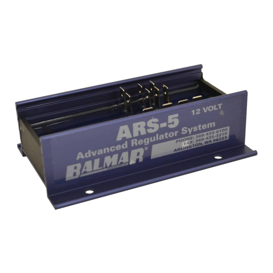
Balmar ARS-5 Installation And Operation Manual - Page 3
Browse online or download pdf Installation And Operation Manual for Industrial Equipment Balmar ARS-5. Balmar ARS-5 16 pages. Multi-stage voltage regulator
Also for Balmar ARS-5: Installation And Operation Manual (20 pages), Quick Start Manual (2 pages)

ARS-5 Regulator Terminal Layout
1.
GROUND INPUT
- Connects regulator to system
ground via alternator ground terminal. BLACK wire
included in Ford style plug.
2.
POWER INPUT
- Supplies all power to operate the
regulator, and provides a source of sensing voltage
for the regulator to control charging output. RED wire
included in Ford-style plug.
3.
IGNITION INPUT
- Connects to a switched source
of battery voltage (to ignition switch or oil pressure
switch). BROWN wire in regulator wiring harness.
4.
FIELD OUTPUT
- Provides excitation voltage to con-
trol the rate of alternator output based on battery volt-
age. BLUE wire in regulator wiring harness.
5.
BAT. TEMP. (+)
- For use with optional BATTERY
Temperature Sensor (MC-TS-B). Sensor lug con-
nects to negative battery post, enabling regulator to
monitor and respond to battery temperature condi-
tion. USE CARE TO ENSURE POSITIVE AND NEG-
ATIVE WIRES ARE CONNECTED TO THE APPRO-
PRIATE REGULATOR TERMINAL.
6.
BAT. TEMP. (-)
- For use with optional Battery Tem-
perature Sensor (MC-TS-B).
7.
STATOR IN
- Connect to WHITE wire included in regu-
lator wiring harness.
8.
TACHOMETER OUT
wire when using stator output to provide a signal for
an electric tachometer. NOT REQUIRED when a me-
chanical tachometer is used.
9.
ALT. TEMP. (+)
perature Sensor (MC-TS-A). Sensor lug connects to
rear case bolt of alternator, enabling regulator to moni-
tor and react to alternator over-temperature condition.
USE CARE TO ENSURE POSITIVE AND NEGATIVE
WIRES ARE CONNECTED TO THE APPROPRIATE
REGULATOR TERMINAL.
10.
ALT. TEMP. (-)
perature Sensor (MC-TS-A).
11.
DASH LAMP
following conditions: Low charging voltage (<12.7V),
high charging voltage (>15.5V), high alternator tem-
perature (>105°C), high battery temperature (>52°C),
or no stator output (if activated in basic program mode).
500 mA maximum.
- 3 -
- Connect to tachometer sender
- For use with optional Alternator Tem-
- For use with optional Alternator Tem-
- provides a source of ground under the
