CAMERA LINK PHRONTIER PHIRE PHR-85-S07 User Manual - Page 7
Browse online or download pdf User Manual for Adapter CAMERA LINK PHRONTIER PHIRE PHR-85-S07. CAMERA LINK PHRONTIER PHIRE PHR-85-S07 13 pages. Fiber adapters

MDR26 pin 1 & 26
MDR26 pin 13 & 14
Electrical current
5.3. LED Status Indicators
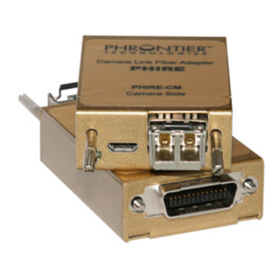
The two LEDs on the front panel of each PHIRE adapter module indicate four operating status
that are described in Table 3 below.
ITEM
LED COLOR
PWR/SYNC
CFG/LOS
5.4. Optical I/O Port
The optical I/O port employs standard industrial small form factor pluggable optical transceivers.
Two fiber models use LC duplex connectors. Single fiber models can accept either SC or LC
simplex connector. The last three digits of the product part number indicate the type of fiber
cable and transmission distance. The letter "M" indicates the system comes with a SFP for
multimode(MM) fiber applications while "S" comes with a SFP for single mode(SM) fiber
applications. Please make sure you have the correct fiber cable before testing the units. For
more information about the fiber cable, please see paragraph 5.5 of this manual.
The PHIRE system you have purchased is designed to accept both multimode and single mode
SFP transceivers. This unique feature provides users with more flexibility and a cost effective
solution to apply the same PHIRE system to different applications that require different link
distance simply by changing the optical transceivers. If you would like to purchase additional
SFP transceivers from Phrontier Technologies, please consult our technical support for
assistance with selecting the correct SFP for your applications.
Inside the two-fiber SFP, the optical transmitter housed in the left LC connector port (when user
is facing the PHIRE unit) converts high speed electrical signals into optical signals which are
transmitted by infrared laser over optical fiber. The optical receiver is located inside the right LC
D-A-CH
FrAnCe – Telecom
Laser 2000 GmbH
Phrontier Technologies
Laser 2000 SAS
82234 Wessling
78860 St-N. l. Bretèche
Tel. +49 8153 405-0
Tel. +33 1 30 80 00 60
www.laser2000.de
www.laser2000.fr
CM Module
Supply 12V DC to camera
Power return
Supply 0.4A to camera
Table 2 PoCL features and pin assignment on MDR26 plug
"Steady On" = power is on and module is operating normally
Green
"Blinking" = module fails to lock camera pixel clock
"Steady On" = module fails on initialization
Red
"Blinking" = loss of optical link
Table 3 LED Functionality Descriptions
FrAnCe – Photonic
PHIRE User Manual V4
Laser 2000 SAS
33600 Pessac
Tel. +33 5 57 10 92 80
www.laser2000.fr
FG Module
Withdraw 12V DC from frame grabber
Power return
Withdraw 0.2 A from frame grabber
OPERATING STATUS
IberIA
Laser 2000 SAS
28034 Madrid
Tel. +34 617 308 236
www.laser2000.es
7
norDICs
Laser 2000 GmbH
112 51 Stockholm
Tel. +46 8 555 36 235
www.laser2000.se
