AkitikA STEREO 400 Quick Start Manual - Page 2
Browse online or download pdf Quick Start Manual for Computer Hardware AkitikA STEREO 400. AkitikA STEREO 400 11 pages. Pc30 replacement

Table of Contents
Table of Contents ................................................................................................................ 2
Table of Figures .................................................................................................................. 2
Section 1: About This Manual ............................................................................................ 3
Who Should Attempt this Project? ................................................................................. 3
Tools You'll Need........................................................................................................... 3
Project Overview ............................................................................................................ 3
Important Safety Notes ................................................................................................... 3
About Components ......................................................................................................... 4
Recommended Solder ..................................................................................................... 4
Warranty ......................................................................................................................... 4
Section 2: Building the PC30 Board ................................................................................... 5
Resistor Installation ........................................................................................................ 6
Diode Installation ............................................................................................................ 6
Regulator Installation ...................................................................................................... 6
Capacitor Installation ...................................................................................................... 8
Removing the Old PC30 ................................................................................................. 8
Installing the new PC30 ................................................................................................ 11
Table of Figures
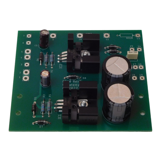
Figure 1-PCB for the PC30 Replacement Board ................................................................ 5
Figure 2-PC-30 connections ............................................................................................... 9
Figure 3-PC30 replacement schematic ............................................................................. 10
Page 2 of 11
