Cameron WHEATLEY 500 Series Installation, Operation And Maintenance Manual - Page 7
Browse online or download pdf Installation, Operation And Maintenance Manual for Control Unit Cameron WHEATLEY 500 Series. Cameron WHEATLEY 500 Series 9 pages. Swing check valve

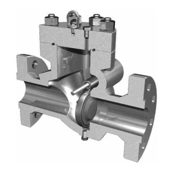
When installing the swing check valve in the horizontal position, install the valve with the arrow mark on the body
pointing in the direction of flow and the bonnet side up.
Flow through the valve (in the direction of the arrow mark) forces the clapper to lift fully. The clapper seals the
valve when the flow is reversed. Gravity causes the clapper to swing closed when no flow is present.
VERTICAL INSTALLATION
When installing the swing check valve in vertical piping, only install the valve with the arrow mark on the body
pointing in the upward direction. Flow upward through the valve will cause the clapper to swing open. This valve
cannot be used with vertical downward flow.
If there is no flow through the piping, gravity will keep the clapper in the closed position. Flow through the piping
in the upward direction will cause the clapper to swing open. When the flow is reversed, the flow and the weight
of the clapper will automatically close the valve.
MAINTENANCE PROCEDURES
CAUTION: Safety practices for pressurized equipment must be followed and address hazards inherent
in pressurized systems. Extreme caution and safety procedures are to be exercised whenever valves, or
fittings on a valve, are serviced or maintained.
The frequency of the maintenance depends on the service conditions. Please contact the factory regarding the
maintenance schedule for particular service conditions.
DISASSEMBLY
No special tools are required to disassemble the valve. With all pressure removed from the associated piping
system, the valves can be serviced in-line or offline.
During in-line maintenance, the swing check valve should be isolated from and relieved of all pressure on both the
upstream and downstream sides. Exercise extreme caution when removing the cover plug on the bonnet, as this
will release any pressure in the valve. Drain the valve fully via the drain plug on sizes 4" and above, or via piping
system otherwise. Remove the bonnet by loosening and removing the nuts. Removing the NPT plugs on both sides
of the body allows for removal of the hinge pin from the bod y. Once the pin is removed, the clapper can be
removed from inside the body.
If replacement of the optional removable seat is required, it is recommended that the valve be removed from the
pipeline. The retaining ring can be snapped out from the groove with a flat head screwdriver before removing the
seat from the seat pocket. Be careful not to damage the seat's sealing face and O-ring groove when removing the
retaining ring.
For offline maintenance, the valve shall be removed from the pipeline.
Inspect the clapper, seat and O-ring seal for wear or possible damage. During the maintenance, replace the clapper
O-ring (integral seat style) and seat O-rings (removable seat style) with new O-rings. Check the retaining ring
(removable seat style) for any damage and change if necessary.
TC-003001-13/ Rev 02
7
