Camille Bauer SINEAX F 535 Operating Instructions Manual - Page 11
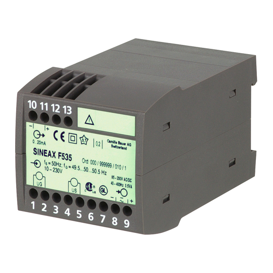
Browse online or download pdf Operating Instructions Manual for Transducer Camille Bauer SINEAX F 535. Camille Bauer SINEAX F 535 12 pages. Transducer for measuring frequency difference

Output
Output signal
10
11
12 13
–
+
4-20mA
SINEAX F 535
Ord: 000/00F535/010/1
fS = 50Hz; fG = 49.5-50-50.5Hz
230-690V
U
U
G
S
1
2
3
4 5
6
U
U
G
S
Measuring inputs
Fig. 5. Declaration to type label.
6. Commissioning and maintenance
Switch on the power supply and the measuring inputs. It is
possible during the operation to disconnect the output line and
to connect a check instrument, e.g. for a functional test.
No maintenance is required.
7. Releasing the transducer
Release the transducer from a top-hat rail as shown in
Fig. 6.
Fig. 6
0,2
Conformity
marks
85-230V DC/AC
40-400Hz 4VA
Works No.
–
+
7
8
9
Power supply
8. Dimensional drawing
112.5
114.1
Fig. 7. Housing type P13/70 onto a top-hat rail (35 ×15 mm or
35×7.5 mm, acc. to EN 50 022).
9. Instruments admissions
Germanischer Lloyd
Type approval certifi cate: 12 261-98 HH
CSA approved for USA and Canada
fi le-nr. 204767
FCC Compliance and Canadian DOC Statement
This equipment has been tested and found to comply
with the limits for a Class A digital device, pursuant to
both part 15 of the FCC Rules and the radio interference
regulations of the Canadian Department of Communi-
cations: These limits are designed to provide reasona-
ble protection against harmful interference when the
equipment is operated in a commercial environment.
This equipment generates, uses and can radiate radio
frequency energy and, if not installed and used in accor-
dance with the instruction manual, may cause harmful
interference to radio communications. Operation of this
equipment in a residential area is like to cause harmful
interference in which case the user will be required to
correct the interference at his own expense.
10
11
12 13
1
2
3
4 5
6
7
8
9
70
11
