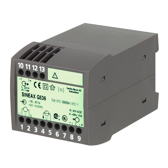
Camille Bauer SINEAX G536 Operating Instructions Manual - Page 13
Browse online or download pdf Operating Instructions Manual for Transducer Camille Bauer SINEAX G536. Camille Bauer SINEAX G536 16 pages. Transducer for phase angle or power factor
Also for Camille Bauer SINEAX G536: Operating Instructions Manual (17 pages)

Application
Phase angle or power factor
measurement
single phase AC current
Phase angle or power factor
measurement
3- or 4-wire 3-phase
balanced load
U: L2 & L3
I: L2
Phase angle or power factor
measurement
3- or 4-wire 3-phase
balanced load
U: L1 & L3
I: L1
Phase angle or power factor
measurement
3- or 4-wire 3-phase
balanced load
U: L3 & L2
I: L3
Phase angle or power factor
measurement
3- or 4-wire 3-phase
balanced load
U: L2 & L3
I: L1
Output
Output signal
10
11
12 13
–
+
0,5
4-20mA
cosphi-linear
SINEAX G 536
Mat: 126830 / 0000000
0.5 - cap - 1 - ind - 0.5
230V 5A 50Hz
L1
U
N
I L1
1
2
3
4 5
6
Input
Measuring range
Measured quantity
Fig. 5. Declaration to type label.
Measuring inputs
Terminal allocation
1
2
4
5
L1/L2/L3
N
1
2
4
5
L1
L2
L3
N
1
2
4
5
L1
L2
L3
N
1
2
4
5
L1
L2
L3
N
1
2
4
5
L1
L2
L3
N
Test marks
85-230V DC/AC
Works No.
40-400Hz 3.5VA
+
–
7
8
9
Power
supply
Application
Phase angle or power factor
measurement
3- or 4-wire 3-phase
balanced load
U: L1 & L2
I: L1
Phase angle or power factor
measurement
3- or 4-wire 3-phase
balanced load
U: L3 & L1
I: L3
Phase angle or power factor
measurement
3- or 4-wire 3-phase
balanced load
U: L2 & L1
I: L2
Phase angle or power factor
measurement
3- or 4-wire 3-phase
balanced load
U: L1 & L2
I: L3
Phase angle or power factor
measurement
3- or 4-wire 3-phase
balanced load
U: L3 & L1
I: L2
6. Commissioning and maintenance
Switch on the power supply and the measuring input. It is
possible during the operation to disconnect the output line
and to connect a check instrument, e.g. for a functional test.
No maintenance is required.
7. Releasing the transducer
Release the transducer from a top-hat rail as shown in
Fig. 6.
Fig. 6
Terminal allocation
1
2
4
5
L1
L2
L3
N
1
2
4
5
L1
L2
L3
N
1
2
4
5
L1
L2
L3
N
1
2
4
5
L1
L2
L3
N
1
2
4
5
L1
L2
L3
N
13
