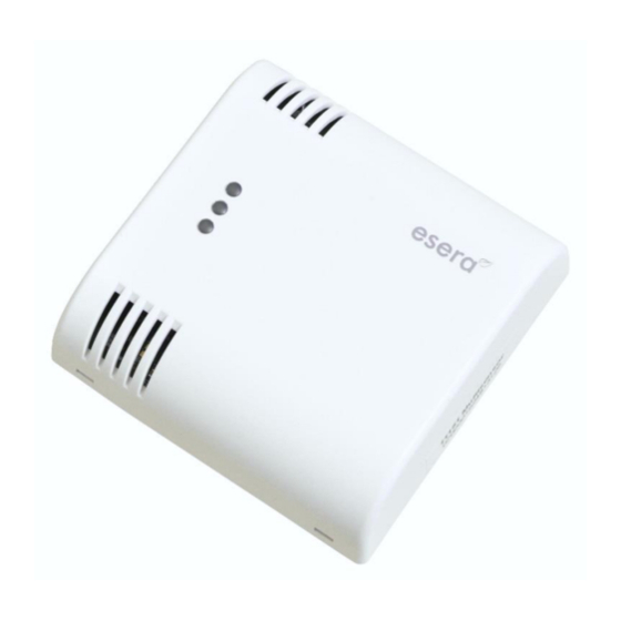
esera automation Multisensor Pro 11150 User Manual - Page 4
Browse online or download pdf User Manual for Accessories esera automation Multisensor Pro 11150. esera automation Multisensor Pro 11150 5 pages. 1-wire sensor for temperature and air humidity w/auto-e-connect

13
Connection
The 1-Wire Multisensor Pro is connected by screw terminals.
The connection terminal is intended for solid cables with 0.2 to
2.5qmm or fine wire cables with 0.2 to 1.5qmm cross-section.
For the connection we recommend slotted screwdriver size
2,5x75.
The pin assignment is printed on the circuit board.
The correct polarity must be observed during connection.
The Multi-sensor must be connected with three cables (ground,
1-Wire Data and 5V). Parasitic mode is not supported.
Note: Basics and tips for 1-Wire bus systems can be found here:
https://www.esera.de/1-wire-grundlagen/
14
Assembly
The mounting location must be protected from direct sunlight, moisture (e.g. dripping water) and drafts. The
device may only be used in dry indoor rooms and in protected outdoor areas. During installation, make sure
that the ventilation openings are located at the top and bottom. Also note the imprint of the direction of the air
flow on the connection side of the unit
A draught-free location must be selected for installation. The unit is intended for installation inside a living
room as a stationary unit. The 1-Wire multi-sensor can be ideally mounted on a flush-mounted box through
clever housing cut-outs.
15
1-Wire network cabling
For short connection distances no special requirements are needed on the cable used. With unshielded
cables, e.g. telephone cable J-Y(St)Y telephone line 4x2x0,8, 1-wire networks in star or tree cabling of about
30 – 80 m in total can be constructed. For installation we recommend the use of CAT 5-7 network cable. For
cable assignment you will find a recommendation in the download area of this product in our webshop.
In smart homes, commercial buildings and industrial environments, shielded cables, e.g. CAT5 or CAT6
cables must be used. This achieves a very high system stability. One more advantage of cabling with CAT
cable is that a linear bus topology can be achieved despite star-shaped cable routing in buildings. This is
only possible with the 8-core cable construction of a CAT cable. We recommend a linear topology.
When using CAT7 cables, the maximum possible cable length of the entire 1-Wire network is reduced due to
the stronger shielding and the resulting higher cable capacity.
With star or tree cabling by using CAT cables a total length of about 50-100m in total can be calculated,
which corresponds to 1-2 floors in a residential building.
Basically, the wiring should avoid unnecessary cable connections, branching or cable extensions. Each joint
or clamp connection reduces the maximum available network size.
The special feature of the wiring of the Multisensors with 1-Wire BUS technology is that all sensors are
operated via three-wire cable. Both power supply and data communication take place via the bus line.
16
Operating conditions
The multi-sensor is designed for temperature and humidity measurements of air and gases indoors, such as
living spaces, offices, workshops or public facilities. The measured values given under technical data are
limit data for the entire 1-Wire Multisensor and must not be undershot or exceeded, otherwise the sensor
may be damaged.
17
Disposal note
Do not dispose of the device within the household waste! According to the directive
concerning old electrical and electronic appliances, electronic devices must be disposed of
via the collecting points for old electronic appliances!
18
Safety instructions
When using products that come into contact with electrical voltage, the valid VDE regulations must be
observed, especially VDE 0100, VDE 0550/0551, VDE 0700, VDE 0711 and VDE 0860
All final or wiring work must be carried out with the power turned off.
Before opening the device, always unplug or make sure that the unit is disconnected from the mains.
Components, modules or devices may only be put into service if they are mounted in a contact proof housing. During
installation they must not have power applied.
Tools may only be used on devices, components or assemblies when it is certain that the devices are disconnected
from the power supply and electrical charges stored in the components inside the device have been discharged.
All rights reserved. Reproduction as well as electronic duplication of this user guide, complete or in part, requires the written consent of
ESERA GmbH. Errors and technical modification subject to change. ESERA GmbH, ESERA-Automation 2020
www.esera.de
11150 V2.0 R1.0 Manual
Page 4 of 5
