ClearCube R4300 Site Preparation Manual - Page 7
Browse online or download pdf Site Preparation Manual for Extender ClearCube R4300. ClearCube R4300 9 pages. Version 53b12
Also for ClearCube R4300: Quick Start Manual (2 pages), Release Note (1 pages), Quick Start Manual (2 pages), Quick Start Manual (2 pages), Quick Start Manual (2 pages), Firmware Update Manual (3 pages)
POWER REQUIREMENTS
The power draw of a fully populated rack is highly
concentrated, making adequate power circuitry vital for
proper operation. Each chassis, operating at full power, will
draw a maximum current of 12 amps at 120 VAC (6A at 240
VAC) or 1.44 kVA. This power draw can be seen during
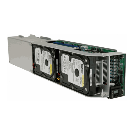
blade boot-up and imaging, when the processors and hard
drives are running at full speed. Normal blade operation will
result in a current draw in the range of 7-9 amps per chassis
at 120 VAC. The chassis power supply is designed to accept
A/C voltages between 100 and 240 VAC. Note: there is an
inverse relationship between voltage and current. Therefore,
if the power system voltage is doubled from 120 VAC to 240
VAC, the current required is halved.
For detailed power requirements on various circuit voltages
(100V, 120V, 208V and 240V), please refer to the Site
Preparation
Checklist
www.clearcube.com/support/.
Consult a professional electrician before attempting ANY electrical system modifications!
After ensuring that adequate power can be supplied to the chassis, the next site concern is power
protection. ClearCube recommends one 15 A (at 120 VAC) circuit breaker to be allocated for
each chassis, with another appropriately sized circuit breaker protecting each rack. If a customer
uses uninterruptible power supplies, sizing should be based on the requirement to supply 9 A (at
120 VAC) to each chassis for the desired duration. Customers should also make sure that the
UPS will pass through enough current to the chassis even while charging. A 3 kVA UPS will, at
most, support two chassis. Refer to Table 1 below for additional information for minimum UPS
sizing. Finally, installation sites will require surge protection for both the chassis in the Data
Center as well as the C/Ports at the desktop. Although the C/Ports do not require much power,
they can sustain damage from power surges in the electrical system.
Table 2: Minimum UPS sizing required for Chassis
Cabling Infrastructure
Each fully loaded chassis will require eight Category 5 cables with RJ-45 connectors for
connecting the PC blades to the C/Ports at user's desktops and eight network cables for
connecting the PC blades to the Ethernet network switch. These cables are not included with the
ClearCube equipment. Short, color-coded Category 5 cables ARE provided with each chassis for
sparing, administration and management daisy-chain connections.
spreadsheet
available
# of Chassis UPS Size
2
3 kVA
3
5 kVA
5
8 kVA
7
Installation Experiences:
Sites other than Data Centers
may not have adequate pre-
installed power. Customers who
intend to place several chassis
in telecom closets or other
backrooms may need to expand
the site power system so that
adequate power will be delivered
to the chassis.
Surge
suppression
desktop is vitally important, as
C/Ports can be damaged when
an electrical storm disrupts the
at
site's power distribution system.
at
the