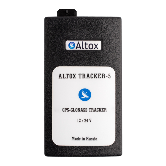
Altox TRACKER-5 Operation Manual - Page 2
Browse online or download pdf Operation Manual for Automobile Accessories Altox TRACKER-5. Altox TRACKER-5 8 pages.

General Information
Dear buyers of ALTOX equipment!
We thank you for purchasing a new ALTOX TRACKER-5. This device will
provide you with great options to control the location, fixation and display
of routes and parking of your vehicle.
You need a SIM card for your ALTOX device. It is recommended to use
special plans for M2M equipment.
Use
Using ALTOX system you can remotely control the location of your vehicle
via SMS text messages and/or GPS-GLONASS monitoring system ALTOX
SERVER 2.0 in the real-time mode (setting TRACKING1). If there is no GSM
connection, the device saves over 10,000 into embedded memory.
ALTOX device uses Wialon IPS v1.1 protocol which allows using other
monitoring systems that support this protocol.
Control and Programming
Algorithm for the connection of the device to the monitoring system:
-
Register an account in ALTOX SERVER 2.0 or any other monitoring system
that supports Wialon IPS v1.1 protocol;
- If needed change server IP address and port in the device using SMS-
commands "SERVER1" and "SERVER2", respectively;
- Ask your mobile provider for APN access point and set is up using SMS-
commands "APN1", "APN2" and "APN3";
- Request the device ID by SMS command "ID1" or "ID2";
- Add a new item with this ID to the monitoring system.
Control via an Outgoing call
Call the phone number of the SIM card installed in the GPS tracker.
The phone number you are using to make a call should already be saved in
the device (see text messages SMS-commands NUM1/2/3).
Saving of the first caller's phone number into cell NUM1 follows up
automatically (cell NUM1 should be empty).
When setting CALL1 is activated, ALTOX tracker responds to the call, then
you need to enter a DTMF-command :
- Switch ON/OFF OUT1 – press 1.
- Switch ON/OFF OUT2 – press 2.
- Request status message – press 4.
- Request account balance message – press 5.
After a minute the connection is dropped automatically.
If CALL0 setting is active, the incaming call is dropped, and OUT1 reverses
its state.
Вид SMS статус сообщения:
Date: 01.01.16
- дата определения местоположения
Time: 00:00:00 (UTC)
- время нулевого часового пояса
GSM (0-31): 28
- уровень приема сигнала GSM (не менее 10)
GPS: 15,0
- количество спутников и параметр HDOP
Speed: 0km/h
- текущая скорость
Volt: 12.8V
- напряжение бортовой сети автомобиля
I/O: 0/0,0
- состояние входа IN и выходов OUT1 и OUT2
http://google.com/maps - ссылка на Google Maps с текущей позицией
Технические характеристики
Параметр
Напряжение питания
Ток, потребляемый в режиме ожидания
Максимальный ток выходов OUT1 и OUT2
Рабочая температура
1 - Красный - Питание +12В (через предохранитель 1А)
2 - Синий
- Дополнительный вход/выход
3 - Черный - Питание GND (общий)
1 4
4 - Зеленый - Вход IN (ожидает появления GND)
2 5
5 - Белый
- Выход OUT1 (коммутирует GND)
6 - Желтый - Выход OUT2 (коммутирует +12В)
3 6
1. Отключить запрос PIN-кода SIM-карты.
2. Установить SIM-карту в слот и тонким
3. Чтобы изъять SIM-карту, продавите ее в
LED
Работа светодиода LED (в слоте SIM)
Светится постоянно - опрос SIM-карты, поиск и регистрация в сети
Вспышки 5раз/1сек - установка GPRS соединения/RING/SMS/USSD
Вспышки 1раз/2сек - режим ожидания, соединение с сервером
установлено (в настройках прописана APN-точка)
(!) отсутствует сигнал GPS-GLONASS
Вспышки 2раз/2сек - режим ожидания, соединение с сервером
установлено (в настройках прописана APN-точка)
есть сигнал GPS-GLONASS
Значение
10В - 28В
менее 30мА
150мА
от -40 до +80°С
предметом продавить до щелчка.
слот тонким предметом до щелчка.
