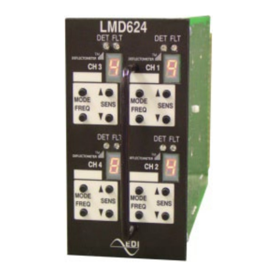
EDI LMD624T Series Operation Manual - Page 14
Browse online or download pdf Operation Manual for Measuring Instruments EDI LMD624T Series. EDI LMD624T Series 15 pages. Deflectometer, inductive loop monitor

4.6 RESPONSE TIMING
These tables assume that all channels are set to the same Sensitivity Level.
4.6.1 LMD622 SERIES RESPONSE TIMING
Sensitivity Level
9
8
7
6
5
4.6.2 LMD624 SERIES RESPONSE TIMING
Sensitivity Level
9
8
7
6
5
4.7 LMD622, LMD622T CONNECTOR PIN ASSIGNMENTS
Pin
Function
A
Logic Ground
B
Detector Unit DC Supply
C
External Reset
D
Channel 1 Loop Input
E
Channel 1 Loop Input
F
Channel 1 Output (+)
H
Channel 1 Output (-)
J
Channel 2 Loop Input
K
Channel 2 Loop Input
L
Chassis Ground
M
Reserved
N
Reserved
P
Reserved
R
Reserved
S
Reserved
T
Reserved
U
Reserved
V
Reserved
W
Channel 2 Output (+)
X
Channel 2 Output (-)
Y
Reserved
Z
Reserved
Pin 1 through 22 is on the top (component) side and pin A through Z is on the bottom
(solder) side. Polarization keys are located at three positions:
Between B/2 and C/3
Between M/11 and N/12
Between E/5 and F/6
Eberle Design Inc.
LMD622 and LMD624 Series
Operations Manual
Response
Sensitivity Level
76-96 ms
38-50 ms
18-24 ms
9-12 ms
5-7 ms
Response
Sensitivity Level
162-217 ms
77-102 ms
38-51 ms
21-28 ms
12-18 ms
Pin
Function
1
Channel 1 Timing Control (LMD622T)
2
Channel 2 Timing Control (LMD622T)
3
Reserved
4
Channel 1 Redundant Loop Input
5
Channel 1 Redundant Loop Input
6
Reserved
7
Channel 1 Status Output
8
Channel 2 Redundant Loop Input
9
Channel 2 Redundant Loop Input
10
Reserved
11
Reserved
12
Reserved
13
Reserved
14
Reserved
15
Reserved
16
Reserved
17
Reserved
18
Reserved
19
Reserved
20
Channel 2 Status Output
21
Reserved
22
Reserved
Response
4
4-6 ms
3
4-6 ms
2
4-6 ms
1
4-6 ms
--
--
Response
4
11-16 ms
3
11-16 ms
2
11-16 ms
1
11-16 ms
--
--
Page 11
