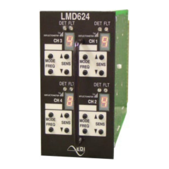
EDI LMD Series Operation Manual - Page 15
Browse online or download pdf Operation Manual for Security Sensors EDI LMD Series. EDI LMD Series 15 pages. Deflectometer, inductive loop monitor
Also for EDI LMD Series: Operation Manual (15 pages)

Between M/11 and N/12
Between E/5 and F/6
4.8 LMD604(T) CONNECTOR PIN ASSIGNMENTS
Pin
Function
A
Logic Ground
B
Detector Unit DC Supply
C
External Reset
D
Channel 1 Loop Input
E
Channel 1 Loop Input
F
Channel 1 Output (+)
H
Channel 1 Output (-)
J
Channel 2 Loop Input
K
Channel 2 Loop Input
L
Chassis Ground
M
Reserved
N
Reserved
P
Channel 3 Loop Input
R
Channel 3 Loop Input
S
Channel 3 Output (+)
T
Channel 3 Output (-)
U
Channel 4 Loop Input
V
Channel 4 Loop Input
W
Channel 2 Output (+)
X
Channel 2 Output (-)
Y
Channel 4 Output (+)
Z
Channel 4 Output (-)
Pin 1 through 22 is on the top (component) side and pin A through Z is on the bottom
(solder) side. Polarization keys are located at three positions:
Between B/2 and C/3
Between M/11 and N/12
Between E/5 and F/6
Eberle Design Inc.
LMD602 and LMD604 Series
Operations Manual
Pin
Function
1
Channel 1 Timing Control (LMD604T)
2
Channel 2 Timing Control (LMD604T)
3
Channel 3 Timing Control (LMD604T)
4
Channel 1 Redundant Loop Input
5
Channel 1 Redundant Loop Input
6
Reserved
7
Reserved
8
Channel 2 Redundant Loop Input
9
Channel 2 Redundant Loop Input
10
Channel 4 Timing Control (LMD604T)
11
Reserved
12
Reserved
13
Channel 3 Redundant Loop Input
14
Channel 3 Redundant Loop Input
15
Reserved
16
Reserved
17
Channel 4 Redundant Loop Input
18
Channel 4 Redundant Loop Input
19
Reserved
20
Reserved
21
Reserved
22
Reserved
Page 12
