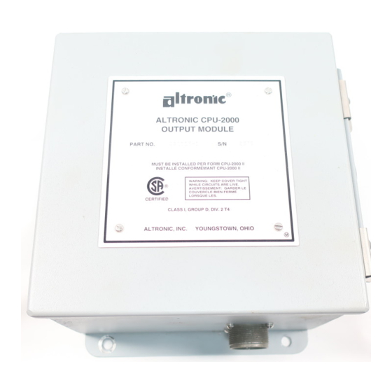
Altronic CPU-2000 Service Instruction - Page 16
Browse online or download pdf Service Instruction for Control Systems Altronic CPU-2000. Altronic CPU-2000 20 pages. Ignition system

6.0 OSCILLOSCOPE TESTS
6.1 TEST SET-UP-Two 100:1 oscilloscope probes are required. Test speed is 360 RPM. NOTE: The
signals being monitored are 290 to 350 volts, negative polarity. It is recommended that these tests
be performed with the Output Module heated to a temperature of 150
6.2 STORAGE CAPACITOR VOLTAGE PATTERN
A.
The trigger input of the oscilloscope should be connected to the "A" primary coil lead.
NOTE: This is a 290 to 350 volt, negative polarity signal.
B.
Connect the oscilloscope reading probe to the "N" lead of the output connector to view the "A"
side outputs. To view the "B" side outputs connect the oscilloscope probe to the "V" lead.
Normal capacitor patterns are shown below.
C.
Peak output voltage for the Output Module is:
-290±10 volts for energy level E1,
-320±10 volts for energy level E2,
-350±10 volts for energy level E3.
6.3 MUL Tl-STRIKE TESTS
A.
Set the unit to MULTI-STRIKE mode via the keypad on the Logic Module.
B.
Connect oscilloscope to the "N" lead and view first set of shutdown pattern firings.
C.
Verify "A" firing is followed by three additional firings and the time between the first and fourth
firing is four to five milliseconds (See figure MUL Tl-STRIKE).
D .
Connect the oscilloscope probe to the "V" lead and repeat step C.
0 V.
100 V.
200 V
300 V.
350 V.
0 V
100 V
200 V
300 V
320 V
NORMAL PATlERN - N-LEAD
A
C
E
G
J
L
MULTI-STRIKE • N-LEAD
1--
45as -
Shutdown Patterns
NORMAL PAlTERN - V-LEAD
B
D
f
0 V.
100 V.
200 V
300 V.
350 V.
MUL Tl-STRIKE - V-L[AD
0 V
100 V
200 V
300 V
320 V
1--
45ss -
-16-
°
°
F. (65
C.).
H
K
M
