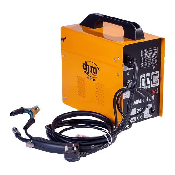
djm direct DJMMIG195 Manual - Page 8
Browse online or download pdf Manual for Welding System djm direct DJMMIG195. djm direct DJMMIG195 15 pages.

- Inserting the welding wire and adjusting the wire guide
- Pull the pressure roller spring and swing it upward.
- Pull the pressure roller holder(E) downwards .
- Swing the screws (F) 90 °and pull off upwards.
- Check the feed roller (G). The appropriate wire thickness must be
specified on the top of the feed roller (G). The feed roller (G) is fitted
with two guide grooves. Turn the feed roller (G) over if necessary or
replace it.
- Position the feed roller holder (G) again and secure it.
- Remove the gas nozzle (10) from the torch (11) by turning it
clockwise, unscrew the contact tube (15). Place the hose package (9)
on the floor as straight as possible pointing away from the welding
set.
- Cut off the first 10 cm of the welding wire to produce a straight cut
with no shoulders, warping or dirt. Deburr the end of the welding
wire.
- Push the welding wire through the guide tube (C) between the
pressure and feed rollers (G) into the hose package mounting (H).
Carefully push the welding wire by hand into the hose package until it
projects out of the hose package by approx. 1 cm at the torch.
- Push the pressure roller holder(E) upwards and Pull the pressure
roller spring(D) and swing it downward.
- Screw the appropriate contact tube for the welding wire diameter
on to the torch and fit the gas nozzle, turning it clockwise.
- Set the adjusting screw for the roller brake (I) so that the wire can
still be moved and the roller stops automatically after the wire
guide has been braked.
10.Operation
Before any work on the machine itself, remove the mains plug from
outlet.
Setting
Since the welding set must be set to suit the specific application, we
recommend that the settings be made on the basis of a test weld.
10.1 MIG Welding principles
MIG (Metal Inert Gas) welding allows you to fuse together two
similar metals without altering the properties of the metal.
A consumable wire electrode is continuously fed through the welding
torch that is fitted with a concentric gas nozzle. the wire is connected
to a high voltage supply which creates an electric arc between the
electrode (the wire) and the workpiece. The arc is used to create the
required heat to turn the metal into a molten state. The wire is used
as both the electrode and as a filler.
The gas is used to prevent oxidation and to shield the arc and the
weld from atmospheric contamination. The choice of gas is
dependent upon the material being welded.
7
