Altronix AL1002ADA220 Installation Manual - Page 4
Browse online or download pdf Installation Manual for Extender Altronix AL1002ADA220. Altronix AL1002ADA220 17 pages. Nac power extender
Also for Altronix AL1002ADA220: Application Manual (8 pages)
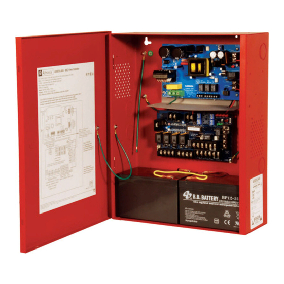
Battery circuits are not power-limited; provide 0.25" spacing from power-limited circuits and use separate
knockout. If additional battery enclosure is required, it must be UL Listed for the application and mounted
within 5' of the AL1002ADA220 enclosure in the same room; minimum 12 AWG wire in appropriate conduit
is required for connection. When using conduit, make sure it is installed in a matter where it can not turn.
5. Set output selection switches marked [OUT1 through OUT4] to follow corresponding
and desired output signal type (Output Programming Selection Table, pg. 4).
6. Connect FACP output to the desired AL800LGK9E logic board inputs, and notification appliances to the
desired AL800LGK9E logic board outputs (see Application Guide).
Note: The 2-wire horn/strobe sync mode will only synchronize horns, horn/strobes, strobes with
synchronization capability.
7. For connection of smoke detectors, digital dialer see Optional Hookup Diagram, pg. 7.
Class A, Style Z Class B, Style W, X, Y, SW1 & SW2 Settings:
• For all Class B, Style W, X, Y hookups SW1 and SW2 on the AL800LGK logic board must be turned OFF.
For all Class A, Style Z hookups SW1 and SW2 on the AL800LGK logic board must be turned ON.
Function
Input to Output
Follower Mode
Temporal Code 3 Mode
Steady Mode
For the above modes DIP Switch 4 determines which Input controls the
corresponding output:
Switch 4 in the ON position causes output(s) to be controlled by Input 1.
Switch 4 in the OFF position causes output(s) to be controlled by Input 2.
- 4 -
Output Programming Selection Table:
Outputs must be programmed independently (OUT1 - OUT4)
Switch Positions
ON
OFF
1
2, 3
3
1, 2
1, 2, 3
Descriptions
Output follows signal it receives from the corresponding
input (i.e. FACP Sync module - maintains synchronization of
notification appliance circuit).
Enables Temporal Code 3 signal generation output.
This mode will accept a steady or a pulsing input.
A steady output signal will be generated.
This mode will accept steady or pulsing input.
input [IN1 & IN2]
AL800LGK9E Board
Output DIP Switches
INPUT SELECT
TEMPORAL
STROBE SYNC
IN>OUT SYNC
AL1002ADA220 Installation Guide