Altronix eBridge Plus 100TM Installation Manual - Page 2
Browse online or download pdf Installation Manual for Transceiver Altronix eBridge Plus 100TM. Altronix eBridge Plus 100TM 4 pages. Ip and poe/poe+ over coax hardened transceiver
Wiring methods shall be in accordance with the National Electrical Code/NFPA 70/ANSI, and with all local codes
and authorities having jurisdiction. Wiring should be UL Listed and/or Recognized wire suitable for the application.
eBridge100TM is not intended to be connected to outside plant leads and should be installed indoors within the
protected premises. eBridge100TM is intended for indoor use only.
1. Secure unit to desired mounting surface with a proper fastening device utilizing the case'smounting hole
(Fig. 2a, pg. 3). Unit should be mounted in proximity of camera/device.
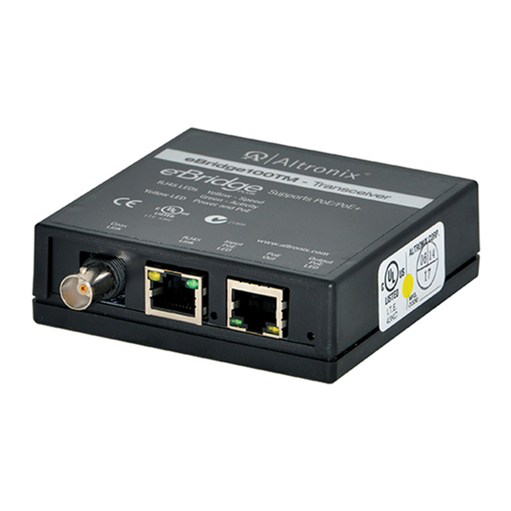
2. Connect structured cable from IP camera/device to RJ45 jack marked [PoE Out] (Figs. 2, 3, pg. 3).
3. Coax: Connect Coax cable from eBridge receiver (eBridge100RM, eBridge400PCRM, eBridge800PCRM,
eBridge1600PCRM or eBridge800E) to BNC connector marked [Coax] (Figs. 2, 3, pg. 3).
CAT5 or higher (must use eBridge100RM receiver): Connect CAT5e or higher to connector marked
[RJ45 IN] (Fig. 2, pg. 3).
Note: eBridge100TM is designed to accommodate Megapixel, HD720, HD1080 and VGA (SD) cameras. It is
important to note that some high resolution and high frame rate cameras may demand faster headend processing
ability, such as a PC graphics card to present a quality image. If the headend processing equipment is insufficient
in speed, the image may show pixelation and latency. It is advisable to pretest system if unsure. Alternatively,
frame rate and resolution may be reduced to accommodate system equipment.
Parameter
Connections
Input Power
Requirements
Indicators
Environmental
Conditions
Regulatory
Compliance
Weights (approx.)
––––––––––––––––––––––––––––––––––––––––––––––––––––––––––––––––––––––––––––––––
*Note: Caution: once PoE connection is established between a receiver and eBridge100TM, disconnection from
eBridge100TM will not disable the PoE output voltage on the receiver. Although eBridge100TM can be reconnect-
ed, caution should be taken not to connect the CAT5 or single UTP wiring from the receiver to any non-PoE device.
eBridge100TM Installation Guide
Installation Instructions:
Technical Specifications:
Description
BNC for Coax link. RJ45 for extended Ethernet link.
PoE compliant to IEEE 802.3af (15W) and
PoE+ compliant to IEEE 802.3at (30W) from eBridge100RM,
eBridge400/800/1600PCRM or eBridge8E.
Yellow (RJ45 connector):
Green (RJ45 connector):
Green:
Operating Ambient Temperature: UL60950-1
eBridge100TM:
For 15W:
For 25W:
For 30W:
Storage Temperature:
Humidity: 20 to 85%, non-condensing.
Operating Altitude: -304.8 to 2,000m.
UL/cUL Listed for Information Technology Equipment (UL 60950-1).
CE European Conformity. C-Tick compliant.
Product: 0.22 lb. (0.1 kg) | Shipping: 0.4 lb. (0.18 kg).
On - Link,
Off - No Link,
Blinking - Activity.
On - 100Base-TX,
Off - 10Base-T.
PoE Active.
– 40ºC to 75ºC (– 40ºF to 167ºF).
– 40ºC to 70ºC (– 40ºF to 158ºF).
– 40ºC to 49ºC (– 40ºF to 120.2ºF).
– 40ºC to 75ºC (– 40ºF to 167ºF).
- 2 -