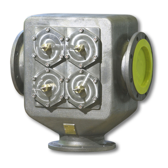
AKO 227.0520 Series Mounting And Servicing Instructions - Page 8
Browse online or download pdf Mounting And Servicing Instructions for Thermostat AKO 227.0520 Series. AKO 227.0520 Series 10 pages. Temperature regulator selfactuated, three-way temperature regulator with interior thermostat, balanced, with flange connections

Mounting and Servicing Instructions
AKO Temperature Regulator selfactuated
7.2 Installation of the Valve
Install the valve with the operating element connection suspended downwards. The
connecting position of the flanges has to follow the function of the control valve. Below the
opening temperature the way A-B is opened. Connection B is always connected to the bypass.
Connection C is always connected to the heat exchanger.
Example of installation of a temperature valve at a heat exchanger
1 temperature regulator
2 strainer
3 shut-off valve
8. Emergency manual adjustment
The thermostats described here are partly equipped with an emergency manual
adjustment in order to comply with the safety requirements - especially those of the
classification companies. This emergency manual adjustment is not to be used for
adjustment during automatic operation. If the thermostat fails, the control valve can be used
as a manually operated three-way valve via the emergency manual adjustment and therefore can
be set in any position until the thermostat can be repaired or replaced.
9. Operation of the emergency manual adjustment
On delivery, the adjusting screw of the manual adjustment is secured in the starting
position with a counter nut. If the thermostat fails, this counter screw is released and the
adjusting screw is adjusted in a clockwise direction using the offset screw driver DIN 911
which is included in delivery. In doing so the tubular slider above the pressure plate is opened
to the cooling path (C), and at the same time the short circuit path (B) is throttled. Between both
end positions any position of the tubular slider is possible so that whilst monitoring the
thermometer the operating temperature can be reached. You must make sure that after every
adjustment the counter nut is fastened tightly again. When installing a new thermostat the
adjusting screw must be put back into its original position so that the path to the cooler (C) is
not mechanically opened first, as this gap cannot be closed again by the automatic system.
Friedrich-Sertürner-Straße 14 • D-51377 Leverkusen • Tel.: +49 (0) 214 / 840599-0 • Fax: +49 (0) 214 / 840599-29
AKO Regelungstechnik GmbH & Co KG
eMail: info@akomail.de • Web: http://www.ako-regelungstechnik.de
8
