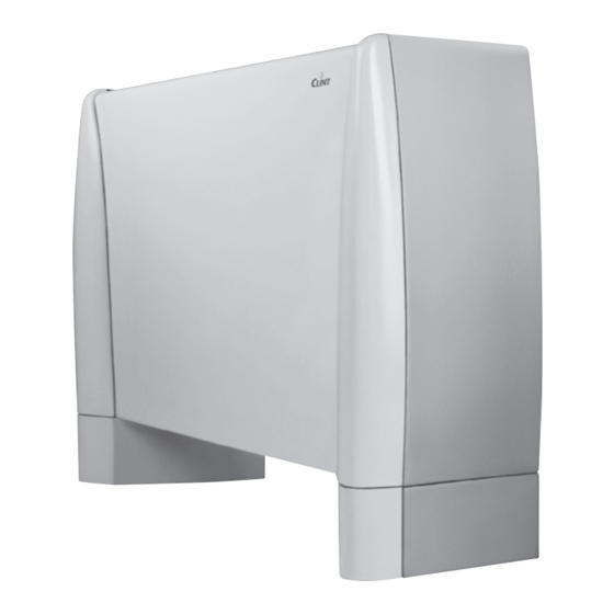
Clint FVW 12 Instructions For Installation, Use And Maintenance Manual - Page 2
Browse online or download pdf Instructions For Installation, Use And Maintenance Manual for Chiller Clint FVW 12. Clint FVW 12 8 pages. Fan coil units

G. I. Holding S.p.A. Vi ringrazia per la fiducia concessagli nell'acquisto del ventilconvettore.
Il manuale deve essere letto completamente ed attentamente. Le diciture "Pericolo" o
"Attenzione" riportate nelle norme d'uso devono essere oggetto di particolare attenzione; se
non osservate possono essere causa di danno al ventilconvettore e/o a persone e cose.
G. I. Holding S.p.A. declina ogni responsabilità per eventuali danni provocati dalla non attenta
lettura del presente manuale o da un uso improprio del ventilconvettore.
Per eventuali anomalie non indicate su questo manuale si prega contattare tempestivamente
il servizio assistenza tecnica.
Attenzione!
Conservare i manuali in luogo asciutto per evitare il deterioramento, per eventuali
consultazioni future.
Prestazioni / Performances
Modello 2R - 3R - 4R
Portata aria
Air flow
Pressione sonora
Sound pressure level
(1)
Alimentazione elettrica
Supply voltage
Potenza assorbita
Absorbed power
Attacchi idraulici
Water connections
Peso
Weight
Alla distanza di 1 m e tempo di riverbero 0,5 s.
(1)
Pressione massima di esercizio 1000 kPa.
Temperatura massima acqua in ingresso 90 °C.
L'acqua può essere addizionata con glicole etilenico inibito.
Dimensioni, caratteristiche tecniche e componenti / Dimensions, technical characteristics and components
1.1 Dimensioni / Dimensions
Telaio interno / Internal frame
1
A
B
D
C
2
E
4
1.2 Caratteristiche tecniche
Il ventilconvettore è una unità terminale per il trattamento dell'aria degli
ambienti nel periodo estivo e invernale. Le versioni sono:
VP Unità verticale con mantello (ripresa inferiore e mandata verticale)
VH Unità verticale con mantello (ripresa frontale e mandata verticale)
VE Unità orizzontale con mantello (ripresa posteriore e mandata orizzontale)
VO Unità orizzontale con mantello (ripresa inferiore e mandata orizzontale)
1.3 Componenti
Vano pannelli di comando
1
Vano predisposto per ospitare i pannelli di comando di cui può essere
dotato l'apparecchio.
2
Ventilatore
Di tipo centrifugo direttamente accoppiato a un motore elettrico monofa-
se a 6 velocità, delle quali 3 collegate nella configurazione standard.
max
m
3
med
m
3
min
m
3
max
dB(A)
(1)
med
dB(A
min
dB(A
V/Ph/Hz
max
kW
"G
kg
A
C
3
8
2
A
C
B
G. I. Holding S.p.A. thanks you for your choice in the purchase of this fan coil unit.
This manual must be read completely and carefully. The messages "Danger" and "Warning" in
the usage insructions must be given special attention; if they are not observed there may be
damage to the fan coil unit and/or to persons and things.
G. I. Holding S.p.A. declines any responsibility for any damage caused by inattentive reading
of this manual or by improper use of the fan coil unit.
For any abnormalities not covered by this manual, please promptly contact technical customer
service.
Attention!
Keep manuals in a dry place to avoid their deterioration, for future reference.
12
22
13
23
14
24
/h
240
340
/h
190
260
/h
140
170
41
44
34
38
26
26
<-------------------------------- 230 / 1 / 50 ------------------------------->
0,02
0,04
½"
½"
16
19
At a distance of 1 m and with reverberation time of 0.5 s.
(1)
Maximum operating temperature 1000 kPa.
Maximum inlet water temperature 90 °C.
Inhibited ethylene glycol can be added to the water.
MOD.
A mm
B mm
C mm
D mm
E mm
F mm
G mm
H mm
I mm
L mm
M mm
N mm
Mod.
B
A mm
B mm
C mm
7
D mm
E mm
5
9
6
1.2 Technical characteristics
The fan coil unit is a terminal unit for the treatment of room air in the
summer and winter seasons. The versions are:
VP Vertical unit with cabinet (lower suction and vertical delivery)
VH Vertical unit with cabinet (front suction and vertical delivery)
VE Horizontal unit with cabinet (rear suction and horizontal delivery)
VO Horizontal unit with cabinet (lower suction and horizontal delivery)
1.3 Components
1
Control panel compartment
Compartment provided to house the control panels with which the
appliance may be equipped.
2
Fan
Centrifugal type directly coupled to a 6-speed single-phase electric motor,
with 3 speeds connected in the standard configuration.
32
42
52
33
43
53
34
44
54
430
540
690
340
420
530
250
280
400
40
44
46
34
37
39
25
27
33
0,05
0,07
0,08
½"
½"
½"
24
28
33
12
22
32
42
13
23
33
43
14
24
34
44
440
560
760
960
475
475
475
475
185
185
185
185
416
536
736
936
310
310
310
310
50
50
50
50
85
85
85
85
50
50
50
50
267
267
267
267
148
148
148
148
60
60
60
60
70
70
70
70
12
22
32
42
13
23
33
43
14
24
34
44
690
820
1080 1210 1470 1470 1730
500
500
500
500 500
210
210
210
210 210
90
90
90
90
30
30
30
30
62
72
63
73
64
74
910
1180
730
810
510
590
48
52
43
42
34
34
0,16
0,20
½"
½"
43
54
52
62
72
53
63
73
54
64
74
1160
1135 1410
475
545
545
185
250
250
1136
1111 1386
310
380
380
50
45
45
85
165
165
50
43
43
267
265
265
148
220
220
60
60
60
70
70
70
52
62
72
53
63
73
54
64
74
570
570
275
275
90
90
90
30
30
30
