Clint FVW 23 Instructions For Installation, Use And Maintenance Manual - Page 4
Browse online or download pdf Instructions For Installation, Use And Maintenance Manual for Chiller Clint FVW 23. Clint FVW 23 8 pages. Fan coil units
2.2 Rotazione della batteria
Se per esigenze di installazione fosse necessario ruotare la batteria,
procedere nel seguente modo:
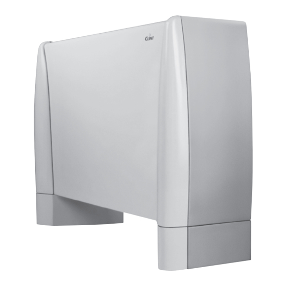
• Togliere il mantello di copertura del ventilconvettore (Fig. A).
• Togliere il pannello di tamponamento
allentando le relative viti.
2
• Sfilare la batteria
dall'unità ventilante dopo aver agito sui punti di
fissaggio (Fig. B).
• Togliere i pretranciati
3
dal fianco sx (Fig. C).
• Inserire la batteria dopo averla ruotata ed infine fissarla.
• Chiudere i fori degli attacchi idraulici rimasti inutilizzati sul fianco dx
con della gomma adesiva
• Spostare il supporto comandi e il relativo cablaggio sul fianco dx del
ventilconvettore (Fig. D).
• Spostare il collegamento di messa a terra
• Spostare la targhetta di tamponamento da sotto lo sportellino di dx
a quello di sx.
• Ad operazioni ultimate rimontare il mantello di copertura.
Fig. A
2.3 Collegamenti elettrici
Prima di effettuare qualsiasi operazione sulla parte
elettrica del ventilconvettore togliere l'alimentazio-
ne spegnendo l'interuttore generale. Ricordarsi
sempre di collegare il filo di terra.
Il collegamento a terra é obbligatorio per legge.
L'installatore deve provvedere alla sua realizzazio-
ne utilizzando l'apposito morsetto contrassegnato
dall'indicazione internazionale di messa a terra.
I collegamenti elettrici devono essere effettuati
come da Fig. E e Fig. F.
2.4 Avviamento
Sfiatare l'impianto dopo averlo riempito.
Inoltre sfiatare il ventilconvettore per mezzo
delle apposite valvoline e controllare il buon fun-
zionamento del ventilconvettore.
Attenzione!
Il primo avviamento del ventilconvettore de-
ve essere effettuato alla massima velocità,
lasciando girare il ventilatore per circa 4/5
ore. Ripetere l'operazione dopo una lunga
inattività.
2.5 Orientamento delle alette delle griglie
• Sbloccare la griglia all'estrema dx estraendo i pio-
lini
(Fig. G);
1
• Spostare tutte le griglie verso dx
dalla sede;
• Orientarle nella posizione desiderata
• Inserirle nella sede e farle scorrere verso sx
• Bloccare l'ultima griglia di dx sfondando il pre-
tranciato in corrispondenza del foro presente nel
mantello o facendo corrispondere l'interspazio fra
le ultime due alette con il foro presente nel man-
5
tello e reinserire i piolini
.
4
1
posto davanti alla batteria
4
.
5
sul fianco dx.
Fig. B
Al comando a bordo macchina (versioni verticali)
Fig. E
2
e sganciarle
Fig. F
3
;
4
;
2
2.2 Coil rotation
If installation requirements make it necessary to rotate the coil, pro-
ceed in the following manner:
• Remov the cabinet from the fan coil unit (Fig. A).
• Remove protection panel
the relative screws.
• Slide coil
(Fig. B).
• Remove the pre-punched pieces
• Insert the coil after rotating it and then fasten it.
• Close the holes of the water connections which are unused on the rh
side with the included adhesive rubber
• Move the control support with its wiring to the rh side of the fan coil
unit (Fig. D).
• Move earth connection
• Remove the closure template below the right door and place it below
the left one.
• When the operation is concluded re-install the cabinet.
Fig. C
Built-in to control (vertical versions)
Connettore
Connector
Al comando remoto (versioni orizzontali)
Remote control (horizontal versions)
Connettore / Connector
1
5
Fig. G
1
located in front of the coil by loosening
2
out from the fan unit after acting on the fastening points
3
from the lf side (Fig. C).
5
to the rh side.
Fig. D
2.3 Electrical connections
Before carrying out any operations on the electri-
cal part of the fan coil unit, disconnect the ele-
ctrical mains power supply by turning off the main
switch. Always remember to connect the earth
wire. The earth connection is required by law.
The installer must provide for its realization by using
the appropriate terminal which is marked with the
international symbol for earth connections.
The electrical connections must be made as
shown in the picture E and picture F.
2.4 Start-up
Bleed the system after having filled it.
Also bleed the fan coil unit by means of the
appropriate valves and check fan coil unit for
proper operation.
Attention!
The first start-up of the fan coil unit must be
made at maximum speed, letting the fan run
for 4-5 hours. Repeat this operation after a
long shutdown period.
2.5 Grilles orienting
• Free the extreme right grille lifting the pins
(Fig. G);
• Shift grilles to the right
• Turn grilles as desired
• Insert grilles and shift them to the left
• Block the last grille on the right punching the
precut hole of the cabinet or putting in cor-
respondence the space between the last two
finns with the hole and reinsert the pins
3
4
.
1
2
and remove them;
3
;
4
;
5
.
0°
270°
90°
180°