Doepke SIRO Series Installation And Operating Manual - Page 2
Browse online or download pdf Installation And Operating Manual for Control Unit Doepke SIRO Series. Doepke SIRO Series 2 pages. Blind control module
Doepke
DE EN
Installation and Operating Manual
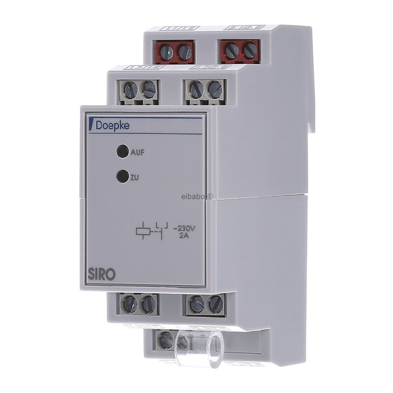
for the SIRO blind control module
General
The SIRO is a system component of the SI building management system and can also
be used for system-independent control functions. The SIRO is suitable for controlling
blinds, shutters, Venetian blinds, awnings and skylight drives.
Control functions
Inputs are controlled with an impulse from the operating voltage (24 V DC ). A continuous
control voltage does not change the switching status.
Terminals
static control inputs priority control/control inputs and outputs: The
output signals of the combined control inputs/outputs A1 and A3 can be
used for an external indication of load contact switch position, but also for
further control functions. By applying a 24 V
control input/output, the blind is moved upwards as a matter of priority.
A1/A3
Priority downwards movement is induced by a 24 V
at the A3 control input/output. When signal is received from the A1 and A3
control inputs/outputs, the control commands to the other control inputs
are saved; the most recently saved control command is executed once the
priority signal is lifted.
dynamic control inputs individual control: Each blind can be moved
into any desired position independently of the others using a keypad. By
A2/A4/A6
pressing the corresponding button on control inputs A2 or A4, the blind
is moved upwards or downwards. Pressing the same button again or the
stop button on A6 will stop the blind an any desired position.
dynamic control inputs group control/central control: A blind group, e.g.
a floor, a side of a building or an entire building can be closed or opened
A5/A7/A6
simultaneously with an impulse to control inputs A7 or A5. Pressing the
stop button A6 will stop the blinds in any desired position.
dynamic control output stop: A stop impulse occurs at output A8
90 seconds after activation of one of the dynamic control inputs. This stop
A8
impulse with a duration of 100 milliseconds can be used for automatic
switch-off by placing a link from A8 to stop input A6.
Important note
Motors with electronic torque monitoring often require a period of freedom from v oltage
of up to 600 milliseconds in order to change direction, which is known as s witching time
(t = 600 ms) and is taken into account by SIRO. Control impulses which occur during the
switching time will cause the switching time to start over again. Once the switching time
has expired, the most recent control command is executed.
In the event of priority control via A1 or A3, the switching time for the additional load
module SIRO-SL is only ensured if the SIRO-SL is controlled via the SIRO relay contacts.
In this case, the SIRO cannot be used for switching a motor. According to the motor
manufacturer, when using capacitor blind motors, parallel switching of several drives
is not generally permitted. The manufacturer's instructions for the drive motors must
always be observed.
Mounting
Installation of the blind control relay may only be carried out by an authorised, trained
technician. Assembly only requires quick fastening on mounting rails.
Warranty
All professionally installed, unaltered devices are covered by warranty during the
statutory warranty period from the day of purchase by the end user. The warranty
is not applicable to damage incurred during transport or caused by short-circuit,
overloading or improper use. In the event of defects in workmanship or material,
which are discovered within the warranty period, the company will provide repair or
replacement free of charge. The warranty will be rendered null and void if the device
is opened without authorisation.
Technical data
SIRO
Operating voltage
Internal consumption
(switched on/off)
A2
A4
Control
A5
inputs
A6
A7
Control voltage
Control current
(dynamic control inputs)
3931104 | 09/2015 | Doepke Schaltgeräte GmbH, Stellmacherstraße 11, D-26506 Norden
continuous signal to the A1
DC
continuous signal
DC
24 V DC ± 10 %
300 mW/25 mW
up/stop
down/stop
central up
central stop
central down
24 V DC ±10 %
max. 1 mA at switching moment
SIRO
Length of control cable
Permitted switch bounce
time
Required control impulse
duration
A8
Control
output
Delay time
A1
A3
Control
Design
outputs
Load rating
Switch status
indicator
Design
1 changeover contact, potential-free, with off position
Switching
time when
changing
direction
Switching
voltage
Load
contacts
Rated current
Switch
ing power
cos φ = 1
Switch
ing power
cos φ = 0.5
Protection class
Housing
Terminals
Max. clamping area
Min. cross-section
Ambient temperature
Design requirements
Load fac
Input
tors in the
load factor
SI building
manage
Output
ment
load factor
system
Weight
Article number
Wiring diagram
ab / stopp
(down / stop)
Kontrolle / Vorrang ab
(control / prirority down)
18
1.1
A1
auf / stopp
1.2
(up / stop)
Kontrolle / Vorrang auf
(control / prirority up)
zentral / Gruppe auf
(central / group up)
SIRO
zentral / Gruppe stopp
A5
(central / group stop)
1.3
B1
zentral / Gruppe ab
1.4
(central / group down)
max. 1000 m for up to 20 parallel inputs
with a diameter of 0.6 mm
max. 10 ms
min. 40 ms
Stop impulse (t = 100 ms)
90 s
Movement direction up
Movement direction down
Semiconductor output
max. 50 mA
via internal LED
600 ms
230 V AC
max. 2 A
500 VA
350 VA
IP40 when installed in distribution board
ABS
Uclamp terminals
1 × 2.5 mm² (solid), 1 × 1.5 mm² (stranded)
0.4 mm
-10 °C to +45 °C
DIN EN 60669
1 ILF
20 OLF
0.224 kg
09500152
L1
N
M
~
15
16
NC
1.5
2.1
2.5
A2
A3
A4
1.6
2.2
2.6
externe Anzeige ab
(external display down)
auf
zu
externe Anzeige auf
(external display up)
A7
A8
A6
2.3
2.7
1.7
Ausgang Stopp-Impuls
(output stop pulse)
B2
1.8
24 V DC
0 V DC