Ashcroft T6500 Installation And Maintenance Instruction - Page 3
Browse online or download pdf Installation And Maintenance Instruction for Measuring Instruments Ashcroft T6500. Ashcroft T6500 6 pages. Pressure gauges with switching contacts
Also for Ashcroft T6500: Installation And Maintenance Instructions (5 pages)

Installation and Maintenance Instruction for
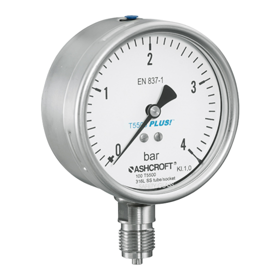
T5500/T6500 Pressure Gauges
with switching contacts
3 Technical data
The detailed technical information can be found in the
documents in the Appendix, Chapter 11.
4 Labeling on the device
The label with the serial number and type designation
and process/ambient temperature range is located on the
outside of the housing. The materials identifier is encoded in
the type designation.
5 Construction and function
5.1
Overview
1.
Bourdon tube
2.
Socket and process connection
3.
Movement
4.
Pointer
5.
Dial
6.
Window
7.
Bayonet ring
8.
Gasket
9.
Vent valve
10. Case
11. Blow-out and compensation plug
5.2
Description of function
The pressures to be compared, differential pressure, act on
a flexible stainless steel diaphragm, which separates the
two pressure chambers.
The sensing element, a bourdon tube (C-form or helical)
that is welded to the socket, will be exposed from inside
with pressure. Under pressure the elastic tube is deflecting
against the zero position. This deflection is proportional
to the adjacent pressure. The movement transfers the
deflection to the pointer which is connected to the contact
(magnetic spring contact) or flags (inductive contact).
The display of the measured value is given on a 270° scale.
5.3
Description of components
5.3.1
Scale with pointer
The pressure gauge is equipped with a dial face and pointer
pursuant to EN 837-1, nominal size 100 mm or 160 mm.
5.3.2
Instrument connenction
The instrument connection is located on the bottom side
(T5500-KF and T6500-KF) or at the back side (T5500-KF) of
the pressure gauge and is a threaded connection.
5.3.3
Vent valve
The vent valve for the housing is located on the top side.
If the nipple is pulled out, the housing is vented and the
pressure which has built up in the housing due to the
influence of temperature is discharged. With the valve
closed, protection class IP 66 is
achieved.
Open valve (position B), wait for
pressure relief and close valve again
(position A). Filled Models need to be
Ashcroft Instruments GmbH
Deutschland / Germany
Max-Planck-Str. 1
D-52499 Baesweiler
Tel.: +49 (0) 2401 808-0
©2018 Ashcroft Instruments GmbH IM-T5500KF-EN Rev. A 11/18
P/N 095I111-01EN
All specifications are subject to change without notice. All sales subject to standard terms and conditions.
ashcroft.eu
For more information on support and
local partners please visit our web
page at ashcroft.eu or follow the
QR-Code
vented before commissioning by opening the air valve on
the upper side of instrument!
5.3.4
Rear wall/plug with blow-out capability
The pressure gauge has a plug capable of blowing out on
the rear wall of the housing (Model T5500-KF) or a rear wall
capable of blowing out (Model T6500-KF). These act as a
safety feature pursuant to EN 837-1 and simultaneously
allow for temperature compensation for the housing, via a
rubber membrane.
5.4
Accessories
Please contact the manufacturer regarding available
accessories.
6 Transport
6.1
Safety
The pressure gauge should be protected against the
effects of knocks and impacts. The device should only be
transported in the packaging provided, to protect against
glass breakage. The device should only be transported in a
clean condition (free of residues of measuring media).
6.2
Transport inspection
The delivery must be checked for completeness and
damage during transport. In the event of damage during
transport, the delivery must not be accepted, or only
accepted subject to reservation of the scope of the damage
being recorded and, if necessary, contact Ashcroft for
instructions.
6.3
Storage
The pressure gauge must be stored in dry, clean conditions,
within a temperature range of -40 to +60 °C, protected
against direct exposure to sunlight and protected against
impact damage.
7 Assembly/Installation
7.1
Safety
To ensure safe working during installation and servicing,
suitable shut-off valves must be installed in the plant (see
5.4 Accessories), enabling the device:
•
To be depressurized or taken out of operation;
•
To be disconnected from the pressure source for
repair or check within the relevant plant;
•
Or to enable function tests of the device to be
performed "on site".
During the works to mount/install the gauge, the plant must
be protected against being switched back on.
7.2
Preparations (requirements for the installation location)
•
A check on suitability of the device for the medium to
be measured, the scope of the measurement range and
static pressure and of the protection against special
conditions such as vibration, pulsation and pressure
spikes.
Page 3
