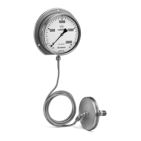
Ashcroft TC Installation And Maintenance Instructions - Page 2
Browse online or download pdf Installation And Maintenance Instructions for Measuring Instruments Ashcroft TC. Ashcroft TC 4 pages. Tank level gauge

Installation and Maintenance Instructions
for the TC Tank Level Gauge
5. INSTALLATION
Considerable care should be taken during installation to
prevent damage and ensure proper performance. It is
recommended that the case be mounted in position prior to
commencing installation; this will reduce the risk of damaging
the instrument's capillary line when it is uncoiled.
Note: If practicable, capillary line should only be disconnected
from the indicator case during installation.
CAUTION
Protect the capillary line's coupling in the event it needs to be
disconnected during routing and installation. Take care when
uncoiling the capillary line while not using the case or seal
housing as leverage points since this could damage the unit
and render it inoperable.
5.1 NOTES
1. Protect the seal housing against the ingress of foreign
matter such as sharp particles or this may puncture the
diaphragm.
2. Support externally routed capillary line with mounting cleats
at intervals of approximately 8 inches (200 mm).
3. Provide mounting cleats at the beginning and completion of
each bend of the capillary line.
4. Despite having a stainless steel case, it is recommended that
a shield be installed where damage may occur.
5. Capillary line should not be routed with a radius less than 2
inches (5 cm).
CAUTION - DISCONNECTING THE CAPILLARY
Disconnecting the capillary should be avoided unless it is
required for routing through a bulkhead or partition wall.
If necessary, the following steps should be followed:
1. Disconnect capillary line at the seal housing; use two
wrenches (17mm).
2. Mount the gauge at installation.
3. Route capillary line through the wall and fasten with cleats at
suggested intervals.
4. Mount the seal housing at tank installation (internal or
external).
5. Thread capillary line to seal housing; use two wrenches (17 mm).
6. Gently open valve between the tank and the seal housing.
CAUTION
Avoid any pressure at the seal housing when disconnecting the
capillary line; disregarding may lead to damage, or injury.
The instrument case may be installed in any orientation to the
seal housing without affecting the gauge reading.
CAUTION
The following should be confirmed prior to installation:
1. Dial references to required specific gravity.
© Ashcroft Inc. 2020, 250 East Main Street, Stratford, CT 06614-5145, USA, Tel: 203-378-8281, Fax: 203-385-0357, www.ashcroft.com
All sales subject to standard terms and conditions of sale. Tank_Content_Gauge_im_RevA_(I&M008-10279)_07-23-20
2. Unit capillary line length.
3. Unit's original installation point had not changed in relation
to the bottom of the tank.
4. Operating temperature reflects original specification.
5.2 INSTALLING THE SEAL HOUSING (EXTERNAL)
The seal housing is bolted to a flange on the side of the tank
(vessel). Installation is measured from the centerline of the
connection point to the bottom of the tank; this requirement
must exactly match that of the initial specification.
Take precautions to ensure that the machined face of the seal
housing is not fouled by any welds or debris.
The diaphragm in the seal housing detects the hydrostatic head
of the tank contents through holes or mesh. There should be no
restrictions between the flange and tank, so proper flow of tank
contents is guaranteed.If not, holes should be drilled.
CAUTION
TO PREVENT DAMAGE TO THE DIAPHRAGM OR SEAL
HOUSING, MOUNTING HOLES MUST BE DRILLED BEFORE
FITTING THE SEAL HOUSING.
The seal housing may be fitted using an Ashcroft isolating
valve. This enables it to be removed without draining the
tank (vessel). Be sure that the tank is completely empty if
the capillary needs to be reconnected after installing the seal
housing.
5.2 INSTALLING THE SEAL HOUSING (INTERNAL)
The seal housing is mounted horizontally on an internal bracket
with the diaphragm facing downward at a predetermined
height from the bottom of the tank; this measurement must be
specified and not altered from that of the initial order.
The connecting capillary line is protected by flexible stainless
steel armored tubing routed inside of the tank to a bulkhead
flange/fitting on the side or top of the tank. Capillary line should
pass through the bulkhead flange or bulkhead fitting and be
adequately supported using best industry practices. Use a
correctly sized spanner to tighten connections.
CAUTION
NEVER TWIST THE INDICATOR OR SEAL HOUSING TO
TIGHTEN CONNECTIONS.
5.3 INSTALLING THE INDICATING CASE
The indicator must be mounted in compliance with standard
industry practice and is designed with an integral back flange
for wall (surface) mounting.
CAUTION
The gauge must not be subjected to:
• Mechanical shock
• Vibration
• Temperature in excess of the unit's recommended operating
temperature
2
