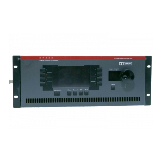
Dolby Laboratories CP500 User Manual - Page 4
Browse online or download pdf User Manual for Computer Hardware Dolby Laboratories CP500. Dolby Laboratories CP500 8 pages. Digital remote controller
Also for Dolby Laboratories CP500: Reference Diagrams (19 pages)

Introduction
The Cat. No. 689 Remote Controller provides the capability to control the Model
CP500 Digital Cinema Processor from multiple remote locations. The unit
features:
N
Film format select
N
Fader and mute functions
N
A simple three-wire interface
N
Projector changeover
Multiple remote controllers may be connected, each simultaneously capable of
controlling the CP500.
Installation
The Cat. No. 689 is packaged in its own housing and may be used stand alone or
installed into a console or wall by removing the top plate from the housing. Four
screws located at the corners of the top plate affix the top plate to the housing. If
the housing is used, the entry for the interface cable is designed to accept common
electrical conduit. See the fold-out manual page for wiring details.
The electrical interface to the CP500 is made over three wires:
N
+24 volt power from the CP500
N
An RS232-like multi-drop duplex data interface signal
N
A ground return wire.
Remove the four screws attaching the top plate to the housing of the Cat. No. 689
and observe the PC board attached to the underside of the top plate. The interface
connector, marked "J1", is located on the lower left corner of the board. Connect
the unit as shown in the wiring diagram.
For compliance with FCC and European EMC requirements, it is necessary to
shield all three interface wire conductors with a braid or foil shield, which
electrically connects the chassis of the Cat. No. 689 to the chassis of the Model
CP500 and is not connected to circuit ground.
Multiple Projectors
In installations containing multiple projectors, it may be desirable to install a
remote controller at each projector. Each Cat. No. 689 can be programmed to
signal the CP500 to changeover to the projector associated with each remote
controller. The projector number is programmed by means of a switch located on
the Cat. No. 689 internal PC board. The switch is a 4 way DIP switch located in
the middle right of the board.
CAT. NO. 689 REMOTE CONTROLLER
