CYP PU-515PL-RX Operation Manual - Page 9
Browse online or download pdf Operation Manual for Extender CYP PU-515PL-RX. CYP PU-515PL-RX 16 pages. Hdbaset lite extender set with poe & 2-way ir

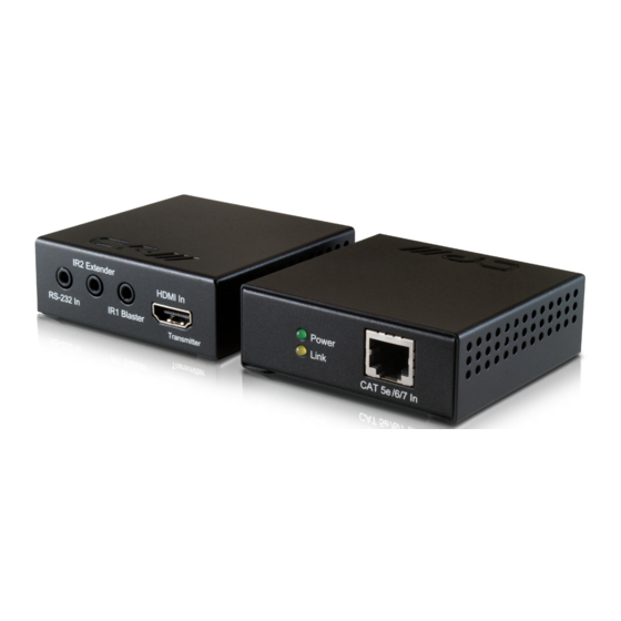
6.2 Receiver Front and Rear Panels
Power
Link
1
2
1
Power LED: This green LED will illuminate when the device is
connected to a power supply.
2
Link LED: This yellow LED will illuminate when both the input and
output CAT5e/6/7 signals are connected. The LED will blink when
there is an error with the transmission signal.
3
CAT5e/6 In: Connect to the transmitter unit with a Single CAT5e/6/7
cable for transmission of all data signals.
4
RS232 Out: Connect to the device that is to be controlled (with
the supplied 3.5mm mini-jack to D-sub 9-pin adaptor) by RS-232
commands
5
IR1 Extender: Connect an IR extender cable for IR signal reception.
Ensure that the remote being used is within the direct line-of-sight of
the IR extender.
6
IR2 Blaster: Connect an IR blaster cable for IR signal transmission.
Place the IR blaster in direct line of sight of the equipment to be
controlled.
7
HDMI Out: Connect to a HDMI equipped TV/monitor for display of the
HDMI input source signal.
CAT 5e /6/7 In
3
IR1 Extender
RS-232 Out
IR2 Blaster
4
5
6
HDMI Out
Receiver
7
9
