DOLD MINISTART GF 9016 Translation Of The Original Instructions - Page 2
Browse online or download pdf Translation Of The Original Instructions for Controller DOLD MINISTART GF 9016. DOLD MINISTART GF 9016 4 pages. Softstarter and softstop device
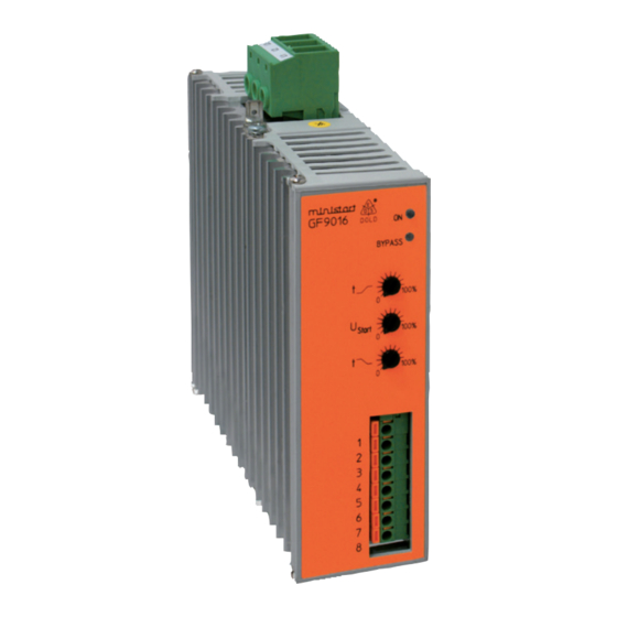
Indication
LED green
ON
=
LED yellow
ON
=
flashes with rising or falling speed at softstart - soft-
stop
flashes with same frequency at error (see table)
LED red: On, when failure detected (only on devices ≥ 25 kW
Failure codes
Fault
LED yellow
yellow LED flashes 1 x times
1
with short space
yellow LED flashes 2 x times
2
with short space
yellow LED flashes 3 x times
3
with short space
yellow LED flashes 4 x times
4
with short space
yellow LED flashes 5 x times
5
with short space
yellow LED flashes 6 x times
6
with short space
yellow LED flashes 7 x times
7
with short space
yellow LED flashes 8 x times
8
with short space
Troubleshooting
In case of a fault, please proceed as follows:
Fault 1:
Electronics supply or motor too small (see technical data minimum motor
load). Send device to the producer to have it checked.
Fault 2:
Check the frequency of starts and the starting current and also observe
the max. ambient temperature. Give the device and/or the motor enough
time between starts to cool down. The heat dissipation can be improved
by forced cooling, e.g., by means of a fan mounted unterneath the device
or by using a motor with a separately driven fan.
Fault 3:
Defect in the internal control electronics. Send device to the producer to
have it checked.
Fault 4/5:
Mains supply is interrupted. Motor lead interrupted, power semiconductor(s)
defective, motor defective. Check motor and wiring. Send device to the
producer to have it inspected.
Fault 6/7:
Mains supply is interrupted. Power semiconductors do not trigger. Motor
rating is too small. Check as to whether the motor is suitable for the device
rating. Send device to the producer to have it checked.
Fault 8:
Mains or motor wiring is interrupted. Power semiconductor(s) defective.
Check wiring. Send device to producer to have it inspected
Motor load must always be connected as continuous operation of the
softstart with no load may cause overheating of the motor and softstart.
It is recommended that the softstart is protected by superfast semiconductor
fuses rated as per the current rating of the softstart or motor. However,
standard line and motor protection is acceptable, but for high starting
frequencies motor winding temperature monitoring is recommended.
Power connected
Power semiconductors bridged
Operating state
Supply voltage error or
load too low
device overloaded /
heat sink temperature to high
failure in electronics
firing error in phase 1
firing error in phase 3
error in motor phase/ power
semicond. defective in phase 1
error in motor phase/ power
semicond. defective in phase 3
general synchronising error
Resetting of faults
The fault message can be reset by disconnecting and reconnecting the
supply voltage.
!
Warning:
At any rate, the cause of the fault has to be identified and remedied by
trained and qualified personnel. Only then must the device be put into
operation again.
Notes
!
Attention:
Please pay attention and consider for the operation of IE3 motors while
dimensioning of softstarters the resulting higher starting currents.
For the use of IE3 motors we highly recommend to dimension and design
the needed softstarters one size higher.
Technical Data
Nominal voltage:
Nominal frequency:
Rated current:
Nominal motor power
at P
at 400 V:
N
Min. motor power:
Start torque:
Ramp time:
Deceleration time:
Recovery time:
Switching frequency:
I
t-Power semiconduct. fuse:
2
Control inputs
Control voltage
Control input current:
Indicator output
Contacts:
Switching capacity
to AC 15
NO contact:
NC contact:
Electrical life
to AC 15 at 3 A, AC 230 V:
Permissible switching
frequency:
Short circuit strength
max. fuse rating:
Mechanical life:
2
3 AC 400 V ± 15 %
(others on request)
50/60 Hz
17
25
32
45
7,5
11
15
22
Approx. 0.2 P
N
40 ... 80 %
0,5 ... 10 s
0,25 ... 10 s
200 ms
60
40
30
10
4000
4000
9100
16200
10 ... 24 V DC
1 ... 2.4 mA
1 changeover contact
3 A / AC 230 V
IEC/EN 60947-5-1
1 A / AC 230 V
IEC/EN 60947-5-1
2 x 10
5
switching cycles
Max. 1 800 switching cycles / h
4 A gG / gL
IEC/EN 60947-5-1
≥ 10
8
switching cycles
11.01.21 en / 335A
A
kW
/
1
h