CYP QU-128 Operation Manual - Page 7
Browse online or download pdf Operation Manual for Amplifier CYP QU-128. CYP QU-128 11 pages. 1 to &/1 to 4/1 to 8 distribution amps

7. Operation Controls and Functions
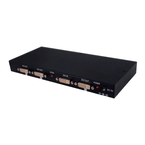
7.1 Front Panel
DVI OUT
①
① DVI OUT 7/8/1: These slots are to connect to the displays with DVI cables.
② SYNC LED: This LED will illuminate in RED when the source signal is
connected and detected by the unit.
③ DVI IN: This slot is to connect with input source equipment such as graphic
card or PC for input signal sending.
④ POWER LED: This LED will illuminate when the power is connected with
power supply.
⑤ DC 5V: Plug the 5V DC power supply into the unit and connect the
adaptor to AC wall outlet.
7.2 Rear Panel
DVI OUT
2
① DVI OUT 2~6: These slots are to connect to the displays with DVI cables.
DVI OUT
7
8
①
DVI OUT
3
SYNC
DVI IN
②
③
DVI OUT
DVI OUT
4
①
4
DVI OUT
POWER
1
①
④ ⑤
DVI OUT
5
6
DC 5V
