Cypress EZ-PD CY4533 Manual - Page 10
Browse online or download pdf Manual for Motherboard Cypress EZ-PD CY4533. Cypress EZ-PD CY4533 20 pages. Barrel connector replacement (bcr) evaluation kit

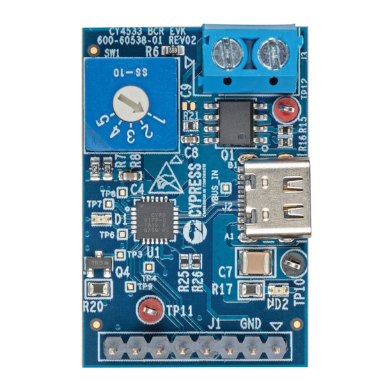
The CY4533 EVK has a green LED to indicate the availability of VBUS and a red LED to indicate a fault with the connection.
A few I/O pins from BCR are taken out on an 8-pin header for use with an external SoC or controller.
2.3.1 EZ-PD BCR Controller Features
Fixed-function USB Type-C and Power Delivery controller supporting USB-PD Rev 3 and Type-C Rev 1.2
Integrated precision Rd and dead-battery Rd termination resistors
Integrated regulator to power from VBUS
Supports a high-voltage P-MOSFET gate driver with slew-rate control
Supports on-chip OVP and UVP to protect system from faults
System level ESD protection on CC, VBUS, DP and DM pins. ±8kV Contact Discharge and ±15kV Air Gap Discharge
based on IED61000-4-2 Level 4C
Available in a 24-pin QFN Package
For more information, refer to the
2.3.2 DC Power Transfer System
Power supplied by the USB Type-C power adapter is sent to an external device or load through a set of back-to-back Power
PMOSFETs. The PMOSFETs are used for the following functions:
Reduce inrush current due to large capacitive loads. The BCR device turns the FETs on slowly to ensure that the inrush
current is limited and controls the rise time of the DC output voltage. The RC circuit of R21 and C8 also help in slowing
the FET turn-on time, and its values can be modified to change the turn-on behavior for application specific needs.
When the VBUS input on the USB Type-C connector is out of range, the BCR device turns the FETs off to protect the
rest of the system.
If the attached USB Type-C power adapter cannot supply the voltages required by the system (as indicated by the resistor
divider selectors), the BCR device turns the FETs off.
The output of the FETs is connected to a two-terminal block J3. The system to be evaluated can be powered using this block.
CY4533 EZ-PD™ BCR Evaluation Kit Guide, Document Number: 002-25263 Rev. *B
BCR
datasheet.
Figure 2-6. VBUS Net and P-FET Load Switch
Hardware
10
