Ashly NE 4200.25 Operating Manual - Page 11
Browse online or download pdf Operating Manual for Amplifier Ashly NE 4200.25. Ashly NE 4200.25 16 pages. Network enabled multi channel power amplifiers
Also for Ashly NE 4200.25: Operating Manual (16 pages)

Operating Manual - NE Multi Channel Power Amplifiers
The Amplifier Control Surface
4) Offset link group - Up to eight groups are available for the purpose of linking similar function parameters
across multiple channels. In addition to the control surface secondary level control (not the main fader), most
DSP functions have a link group check box in their work window to assign a specific parameter to one of the
eight link groups if desired. Link groups can be renamed by clicking on any group name and entering the new
name then pressing <enter> on the keyboard.
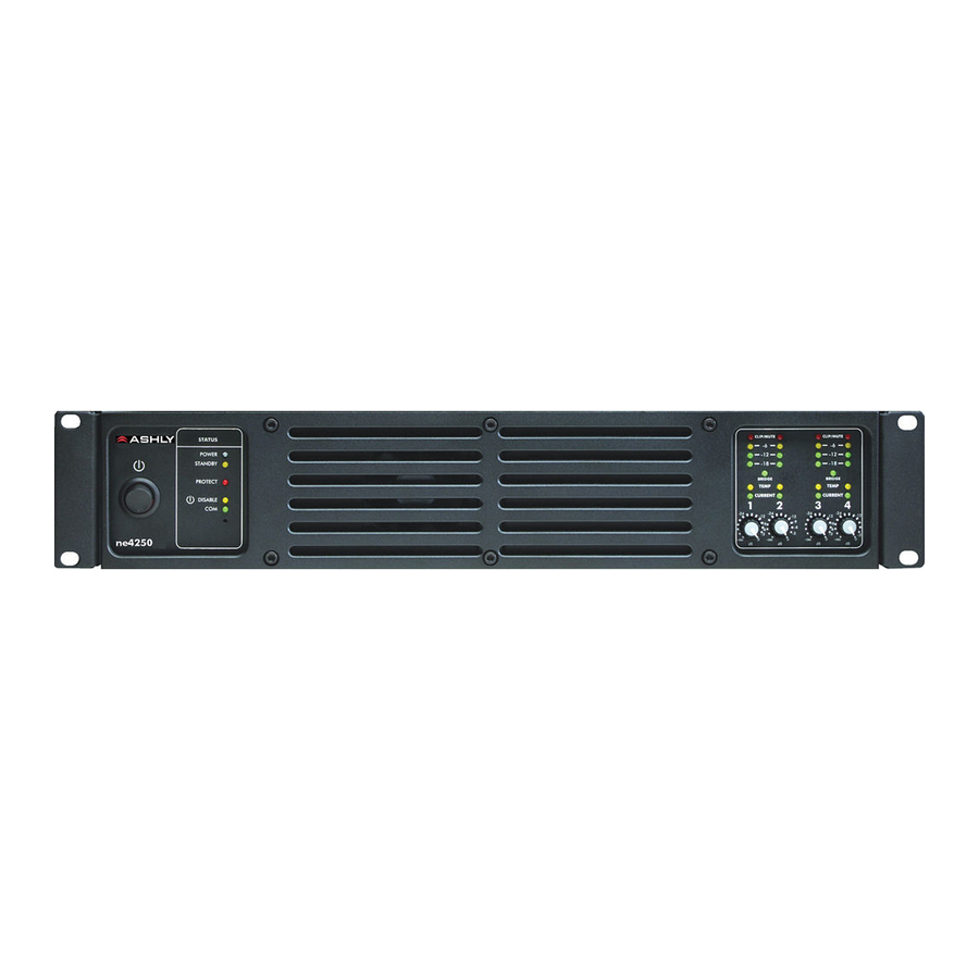
5) Attenuators - These two dials indicate the physical position of hardware controls on either the amp front panel
or the remote level control (if present). Note that these will display the position of attenuators even when
DISABLED in software.
6) Total Attenuation - This indicates the total amount of attenuation being applied to the channel. This is the sum
of the following attenuators: main fader, offset link group attenuation, front panel and remote attenuators (if
enabled).
7) Meters - Input and Output meters display the real time activity per channel, in dB below rated output. Also, the
amplifier's operating temperature and output current are shown. Output current shows that the amplifier
channel is actually delivering output to a connected speaker load.
11
