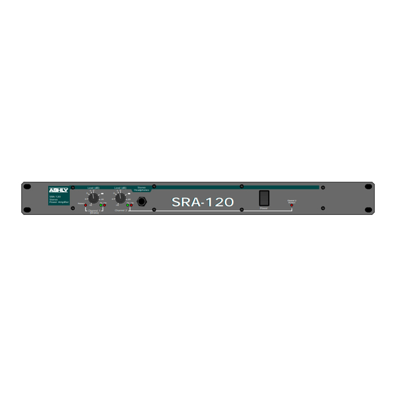
Ashly SRA-120 Operating Manual - Page 10
Browse online or download pdf Operating Manual for Amplifier Ashly SRA-120. Ashly SRA-120 16 pages. Convection cooled amplifier
Also for Ashly SRA-120: Specification Sheet (2 pages)

Operating Manual - SRA-120 Power Amplifier
9.
DESIGN THEORY
Ashly engineers set out to design a single rack
space stereo power amplifier delivering a minimum of
120 watts total with the sonic excellence, mechanical rug-
gedness and unsurpassed reliability Ashly amps are known
for. These qualities were upheld while containing other
important parameters such as weight, depth, serviceabil-
ity and cost.
The result of this design philosophy is a superior
sounding all-discrete bipolar power amp section at the
heart of the amp. The voltage gain stages of the amp are
totally discrete transistors operating "class A" for low
distortion. The output section is a full complementary
bipolar push-pull stage. The active balanced input and
level control stages utilize low-noise op-amps for con-
stant input impedance with accurate, low noise level con-
trol. All integrated circuitry was kept outside the feed-
back loop of the power amp section to maintain excellent
transient response.
10.
TROUBLESHOOTING TIPS
10.1
No Audio Output
• Power switch is on but not illuminated:
Line fuse on rear panel is blown or power outlet
is dead.
IF LINE FUSE IS BLOWN, REPLACE ONLY
WITH SAME TYPE AND RATING FUSE.
• Power switch is lit but no signal present indicator activity:
There is no input signal applied or input level
controls are turned off. NOTE: In MONO mode,
channel two input is disconnected and channel
one input is sent to both channels.
• Protect LED remains lit:
Amp is in thermal protect mode. Loudspeakers
have been disconnected until the amplifier returns
to a normal temperature. The amplifier relies on
convection air currents to move vertically through
the side fins to keep cool. If the protect indicators
come on because of overheating, mount the
amplifier with air space above and below to allow
convection cooling action to occur.
10
A toroidal power supply transformer is used to
minimize induced hum noise and to reduce overall weight.
Epoxy sealed output relays are used to protect speakers
and the amplifier from turn on transients, excessive load
current and overheat conditions. A unique rear-panel sen-
sitivity switch (0dBu or -10 dBu) is provided to interface
the amp with professional line level equipment or directly
with low line level tape machines and CD players.
The SRA-120 is packaged in an extremely rug-
ged one piece welded 14-gauge steel chassis. The power
transformer is located near the front center of the amp to
minimize front panel torsion. Channels 1 and 2 circuitry
are on separate plated-through glass epoxy circuit boards
with plug-in connectors for all wiring to ensure ease of
servicing. Each channel has a large, extruded aluminum
heat sink with vertically oriented fins for maximum con-
vection cooling action.
Amp is protecting speakers from ultrasonic
signals. Disconnect input cables to see if
ultrasonic signal is coming from audio source.
• Protect LED remains lit and relay clicking is heard:
Output is short circuited or load impedance is
too low. Check speaker cables for shorts,
increase load impedance by disconnecting some
speakers.
A high frequency oscillation in the sound system
is occurring when the relays close. Turn down
the input level controls to verify that the amplifier
alone is not causing the problem.
Be sure to use good quality shielded and balanced
input cable. Do not run input cables alongside
output speaker wires over long lengths
(i.e..through the same conduit).
10.2
Distorted Sound
• Output level meters indicate 0dB level (red CLIP LED on):
Amplifier is being clipped. Reduce the signal
level at the signal source.
