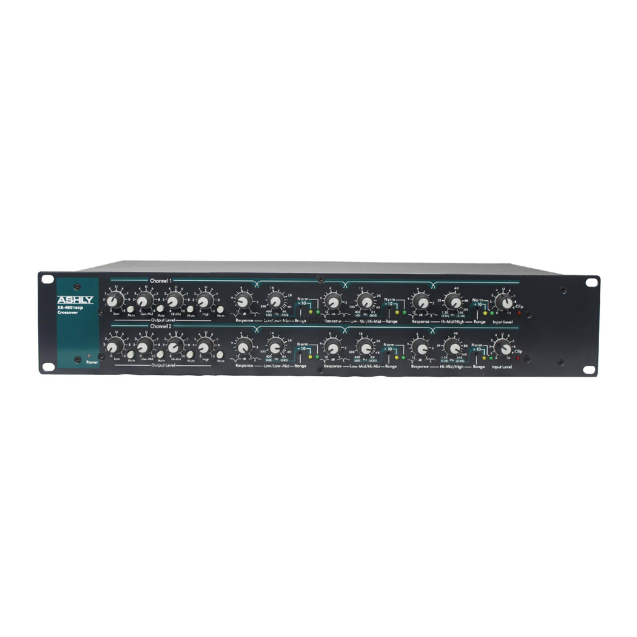
Ashly XR-2001 Operating Manual - Page 7
Browse online or download pdf Operating Manual for Crossover Ashly XR-2001. Ashly XR-2001 13 pages. Stereo 3-way/mono 4/5-way crossover
Also for Ashly XR-2001: Brochure (1 pages), Operating Manual (16 pages), Technical Notes & Specifications (2 pages)

Operator Manual –XR Series Crossovers
XR-1001, XR-2001 and XR-4001 Rear Panels
1.
Inputs - For unbalanced inputs, the signal
should be on the + connection and the -
connection tied to ground. A mono 1/4" plug
used as an unbalanced connection will
automatically be grounded. When using a
stereo plug, or XLR connecto for an
unbalanced signal, the (-) input connection
MUST be tied to ground.
Before connecting to mains power, make sure that the switches are set to the configuration
needed for your particular application. Always switch the crossover off before making
substantial changes to the settings, especially the Range. Failure to do so could result in
damage to the unit or other components in your system. Use four screws and washers when
rack mounting. For mobile use, the unit should be further secured as appropriate.
General Requirements
XR Crossovers have specific physical, electrical and signal requirements for proper
operation. These requirements will vary depending on your specific application, setup, and
the settings on the unit. When setting up and testing your system, please take special care
to double check all connections and settings. Please refer to the specifications section of
this manual for specific input, output and other figures.
AC Power
XR crossovers should be connected to a standard 3-wire grounded electrical outlet
supplying 90-240 Volts, 50-60 Hz. To reduce the risk of ground loop hum, connect all
audio equipment to the same electrical power source. Removal of the ground pin is both
unlawful and dangerous, as a potential shock hazard could result.
This unit will perform normally within the AC voltage range specified above. Voltages
less than this, as found in "brown-out" conditions, may reduce performance. In the event of
a blown fuse, replace only with same type fuse. No user serviceable parts are inside the
chassis. Overall power consumption is less than 15 watts.
2.
Balanced Outputs - This output circuit is an
active output which maintains a constant output
level between the (+) and (-) output terminals,
regardless of either terminal being connected to
ground. This servo-balanced output provides
an unchanged signal without regard to ground.
3.
Power – Switches the unit power on or off.
All Rights Reserved
Page - 7
Safety Instructions – 3
Introduction – 4
XR Crossovers – 5
Connectors & Cables–5
Physical Description – 6
Front Panels
Rear Panels
Installation – 7
General Requirements
AC Power
Typical Applications - 8
Troubleshooting - 10
Dimensions - 10
Specifications - 11
Warranty - 12
