EG4 EG4-LL User Manual - Page 7
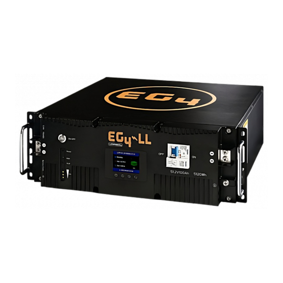
Browse online or download pdf User Manual for Battery Pack EG4 EG4-LL. EG4 EG4-LL 20 pages. Rack mounted 48v 100ah/24v 200ah

Overview
Included Equipment
When you purchase an EG4-LL battery, you will receive multiple items. These items will be included in the
battery box, or separate packaging within your shipment.
1. (1) EG4-LL battery module
2. Inter-battery communication cable
3. Positive and Negative color coded connection cables
Installation
Needed Tools For Installation
The tools required may vary depending on how you choose to mount your battery. In general, you will
need the following items to install your battery into an EG4 racking solution.
1. 10mm socket and ratchet
2. Phillips head screwdriver
3. Torque wrench of proper size
How to Connect Cables to the Battery Terminals
1. Identify the positive and negative terminals on your battery. These are labeled and color coded.
(Red for Positive, Black for Negative)
2. Verify you have all hardware to attach the cable properly. Check to ensure the bolt insert for the
terminal fully seats and can be tightened to the proper torque.
3. Connect the cables to your battery terminals by removing the terminal bolts, inserting them
through the eyelet of the proper cable, and reseating the bolt into the terminal block to the correct
torque.
4. DO NOT finger tighten the terminal bolts. They require a specific torque (60 in-lb/7nm) to ensure
they do not loosen during operation. Failure to properly tighten the terminal bolts can result in
serious damage and will void your warranty.
EG4-LL and EG4 Battery Rack Interface
1. Grounding - One end of the grounding cable is screwed to the grounding hole at the end of the
chassis, and the other end is connected to a grounding lug on the rack (or cabinet) to ensure a solid
connection.
2. Power cable installation - During single battery operation, the battery terminals can directly connect
to the equipment. When there are multiple batteries used in parallel; first use the power cable to connect
each battery in parallel, and then connect to the equipment or switch terminals.
3. Connect the equipment - Clearly identify the location of the positive and negative terminals of the
system, red to the positive terminal, black to the negative terminal, to ensure no connection errors.
6
