Egcon AVR-125 Instructions Manual - Page 3
Browse online or download pdf Instructions Manual for Controller Egcon AVR-125. Egcon AVR-125 7 pages. Automatic voltage regulator
▶
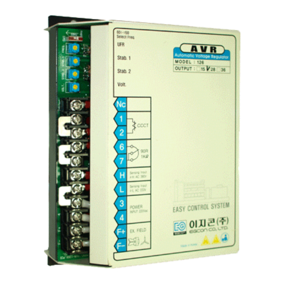
Remote voltage adjust
Remove the jumper from the terminal 6 and 7, and connect the remote voltage adjust
potentiometer (rheostat) to the terminals 6 and 7 as specified.
▶
Sensing voltage
Generator voltage sensing is single-phase 220Vac or 380Vac.
It can be selected in accordance with generator output voltage (or rated voltage)
as follows,
*380V sensing (terminal 4-E1) ; As generator output voltage is380, 400 and
*220V sensing (terminal 4-3) ; As generator output voltage 208, 220 and 230V
▶
Power input
The power input terminal of the regulator are marked power input AC 220V
▶
Power output
The two power output terminals of the regulator are marked F+, F-
These two lines are connected to the F+, F- (or J, K) of exciter field respectively.
6. ADJUSTING
6.1. Start prime mover and bring up to rated speed.
6.2. Voltage would be automatically built up.
If not, confirm until voltage build up through the DC power connection to directly the J,K terminal
of generator ,with BATT. (+) and BATT, (-) under disconnecting lines F+ and F- from the regulator.
6.3. If a minimum residual of 3 VAC is not present, perform field flashing by using 12Vdc battery and
Contactor as below drawing. Please refer to 7.FLASH EXCITING. for details.
6.4. Adjust volt potentiometer until voltage reaches nominal value.
▶
Coarse voltage adjustment
: internal rheostat, single turn
▶
Fine voltage adjustment
: external remote rheostat, single turn, set point should be mid position to notice easily
6.5. Adjust for stab potentiometer if voltage is unstable.
(Adjusting stability changes the response time of regulator,
440V ,415V
3