d&b audiotechnik Ci90 Manual - Page 4
Browse online or download pdf Manual for Racks & Stands d&b audiotechnik Ci90. d&b audiotechnik Ci90 10 pages. Flying bracket
Also for d&b audiotechnik Ci90: Manual (10 pages), Mounting Instructions (11 pages)

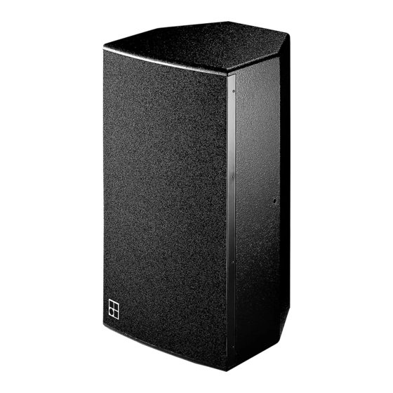
Fig. 1: Ci45/Ci60/Ci90 loudspeaker
1+
1-
2+
passive
2-
crossover
1+
1-
2+
2-
Fig. 2: Connector wiring
IMPORTANT!
Ci45/Ci60/Ci90 Manual
Ci45/Ci60/Ci90
C45i0, Ci60 and Ci90 cabinets are full range, two-way bass-reflex
enclosures each fitted with a 12" LF driver passively crossed over to a
1.4" HF compression driver coupled to a CD horn with 45° x 45° (Ci45),
65° x 40° (Ci60) or 90° x 40° (Ci90) coverage pattern. The cabinets are
designed to allow the horn flares to be rotated through 90° allowing
greater flexibility in placement for a given dispersion.
The cabinets are constructed from marine plywood and have an impact
resistant paint finish. The front is protected by a rigid metal grill fitted
with an acoustically transparent foam. M10 threaded inserts are
provided on the top and bottom, and on the sides of each cabinet, for
mounting rigging accessories. A recess at the top of the rear panel,
which also serves as a handle, is fitted with two Speakon NL4 input
connectors.
Ci45/Ci60/Ci90 systems are designed specifically for permanent
installation. In the standard, upright operating position the CD horn is
positioned below the LF driver so the HF dispersion is less likely to be
influenced by reflections from walls, ceilings or other equipment
mounted nearby. This arrangement improves the headroom before
feedback when systems are flown above the stage.
The frequency response of the systems extends from 18 kHz down to
55 Hz enabling use in most applications without a subwoofer. Where
higher SPLs with an extended bass response are required the Ci systems
can be combined with d&b active subwoofer systems .
CAUTION!
Only operate Ci45/Ci60/Ci90 loudspeakers with a d&b amplifier
configured correspondingly otherwise there is a risk of damage to the
loudspeaker components.
Connections
Since November 2004 the Ci45/Ci60/Ci90 cabinets are fitted with two
NL4 connectors. All pins of both connectors are wired in parallel using
the pin assignments 1+/1−. Using one connector as the input, the
second connector allows for direct connection to additional
loudspeakers.
The systems can be supplied with a fixed cable as an option (cable
H-07-RN-F 2 x 2.5 qmm/AWG 13 with a length of 5.5 m as standard or
length as required). Pin equivalents of NL4 connectors and fixed cable
option (PG) are listed in the table below.
Tab. 1: NL4 and fixed cable (PG) pin assignments
Operation with D12
Selecting Ci60, Ci90 or Ci45 mode in the D12 enables up to two
cabinets to be driven by the respective channel. In applications with low
continuous levels or low ambient temperatures up to three cabinets can
be connected.
(9.1E)
1+
NL4
Brown (+)
PG
1−
2+
Blue (−)
Page 4 of 10
2−
