ambiq micro Apollo4 Blue Plus Quick Start Manual - Page 12
Browse online or download pdf Quick Start Manual for Motherboard ambiq micro Apollo4 Blue Plus. ambiq micro Apollo4 Blue Plus 19 pages.

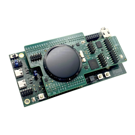
Figure 4 identifies the major components on the Display Shield.
Touch and ALS
Signal Header
Figure 4. Apollo4 Plus Display Shield Parts Locations
The Display Kit has these additional features:
▪ Apollo4 Plus Display Shield
- 1.4" 454*454 Pixel MIPI AMOLED Display
- Display Laminated Capacitive Touch Sensor - TMA525C
- 256 Mb HexSPI Double-Data-Rate (DDR) Enabled PSRAM - APS256XXN
- 64Mb OctalSPI DDR Enabled Flash Memory - IS25WX064
- 4 GB x1/x4/x8 e-MMC Module - THGBMNG5D1LBAIT
- 3-Axis MEMS Accelerometer - ADXL362
▪ Apollo4 Plus AMAP4PEVB Evaluation Board
- USB Type C connector for power/download/debug
- USB Type C connector for power/data to Apollo4 Plus
- Segger J-Link debugger
- Debugger-in port (SWD or ETM)
- Three user-controlled LEDs
- Two push buttons for application use, plus a reset push button
- Power slide switch with LED power indicator
- 3.5 mm Audio Jack (SJ-435107) for evaluating low-power analog audio interface
For a full overview of the Apollo4 Plus EVB's offerings, please refer to the AMAP4PEVB Quick Start Guide,
which includes information about the debug interface.
Caution: The EVB has components loaded on the back of the board. Care should be taken to not damage
these components.
QS-A4PDK-1p0
Apollo4 Plus Display Kit Quick Start Guide
Accelerometer
Load
Switch
1.4" AMOLED
Display
Page 12
NOR
Display signal
Flash
Header
Header
eMMC
Header
eMMC
Memory
2022 Ambiq Micro, Inc.
MSPI1
MSPI0
Header
All rights reserved.
