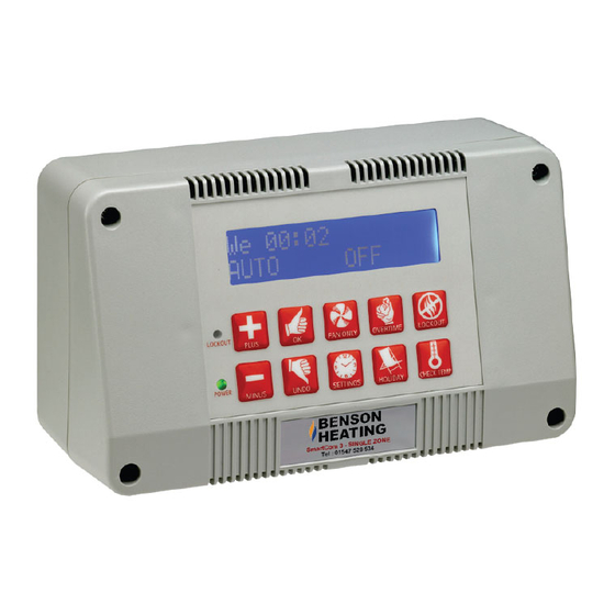
Ambirad SmartCom3 Installation Wiring - Page 8
Browse online or download pdf Installation Wiring for Heater Ambirad SmartCom3. Ambirad SmartCom3 8 pages. Control panel & nor-ray-vac radiant system
Also for Ambirad SmartCom3: Technical Bulletin (4 pages), Manual (14 pages)

1. BMS controlling time only.
Ensure all the programmed ON times in the
SmartCom² are turned off
(i.e. They read "- -:- -").
2. BMS controlling time and temperature.
Ensure all the programmed ON times in the
SmartCom² are turned off
(i.e. They read "- -:- -"). Set all the required
day temperatures to 30°C.
7 End Vent Suction Setting Procedure.
The use of an inverter on the B80, B160, B300
fan system allows the end vent suction to be
adjusted by varying the fan speed.
The description for adjusting the fan speed is
given in the following section. Apart from this
change the commissioning section in the
manual should be followed.
End vent suction (B80, B160, B300 )
For these systems the end vent suction is
adjusted by altering the low speed setting of
the inverter within the local relay unit.
1. Check that the fan damper is fully open
and secure.
2. Ensure the SmartCom³ is in a programmed
ON time.
3. Set the required room temperature above
the actual room temperature.
4. After a 30s delay the fan should run.
5. The fan should now be running and the
inverter should be showing the motor
frequency in the display.
6. Check for correct rotation of fan.
7. Press the mode button 3 times until
'COnF' appears on the display.
8. Press the jog dial to enter. Rotate jog dial
The inverter
interface
(door open)
Mode LEDs
7 segment display
Jog dial:
For navigation when
turned
clockwise or
anticlockwise, or
selection/validation
when pressed.
Registered in England No. 1390934. Registered office: 10 Norwich Street, London. EC4 1BD
AmbiRad UK is a registered trademark of AmbiRad Limited. Because of continuous product innovation, AmbiRad reserves the right to change product specification without due notice.
B.
Remote
door
controllers can be connected to a door
interlock, remote frost stat or permanent off
switch via terminals B2 and B0. When a volt
free connection is provided (ie closed circuit to
enable) at these terminals, the controller
reverts to FROST ONLY mode. Refer to the
individual
wiring
configurations and type.
until 'LSP' is displayed. Press jog dial to
enter. Rotate jog dial to adjust frequency.
Press jog dial to enter new value, causing
the inverter to change its speed. Adjust the
frequency until the appropriate end vent
suction is achieved, this is given in the
table below.
9. Pressing the ESC button twice will return
the inverter to the 'rdY' display. The
setting procedure is now complete.
System
Standard systems
Single 32LR End vent only
Single 38LR End vent only
Single 46LR End vent only
Three 46LR in a single branch
End vent suction (BH300 ONLY)
This unit does not feature an inverter, the end
vent suction adjustment is made using the fan
damper, details of this are given in the
Nor-Ray-Vac manual.
Mode button:
Switches between control/
programming modes.
(Only accessible with door
open).
Escape button:
Exits a menu or
parameter.
The local relay
unit
interlock. SmartCom³
diagrams
for
wiring
End vent
pressure
mbar
6.25
7.5
8.25
9.25
5.6
Technical Support:
Tel:
01384 489 250
Fax:
01384 489 707
www.ambirad.co.uk
