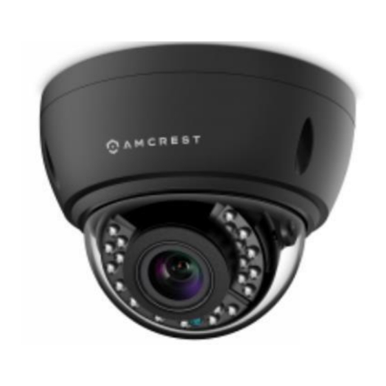
Amcrest AF-2MVD-VARIB Gebruikershandleiding - Pagina 5
Blader online of download pdf Gebruikershandleiding voor {categorie_naam} Amcrest AF-2MVD-VARIB. Amcrest AF-2MVD-VARIB 11 pagina's.

Installation
1) Locate the position in which you would like to place your camera and apply the included mounting sticker to the
surface.
2) Using a drill bit that is the same diameter or slightly smaller, than the included drywall anchors, drill out the
smaller circles on the sticker and insert the drywall anchors.
Note: The drywall anchors should be in the same bag as the screws and are designed to secure the screws to the
mounting surface.
3) Using the included wrench, unscrew the three bolts holding the vandal dome cover to the back plate.
Note: Before proceeding with the next step you will want to break out the cable routing channel with a pair of
needle nose plyers if you wish to mount the camera with the wires outside of the wall or mounting surface.
4) Attach the power and desired video feed cabling.
5) Match the holes of the base plate to the holes on the mounting surface and secure the base plate the to
mounting surface using a Phillips head screwdriver.
6) Position the camera with the framing you desire and secure the vandal dome cover to the base of the camera
using the included wrench.
Connection
This camera series will have three leads at the end of the wiring harness. Their functions are as follows:
Green: TVI,CVI,AHD
Yellow: Analog (CVBS)
Red: DC12V, 2.0A power input
Note: If the proper mode configuration is not set, you will not be able to view your camera on your DVR. Please
make sure you have the proper settings on your camera before you begin setting up or installing.
To connect your camera to your DVR, please follow the steps provided below:
Step 1: Connect a BNC (coaxial) cable to the video out connection of your camera.
Step 2: Connect the male end of the DC power connector of the BNC (coaxial) cable to the female end of the power
connector of the camera.
Step 3: Connect the BNC (coaxial) cable to a video out channel on the back of your DVR.
Step 4: Connect the male end of the DC power connector of the power adapter to the female end of the power
connector of the BNC (coaxial) cable. Plug in the power adapter to apply power to the camera.
For more information on the installation process described, refer to the image below for more details.
5
