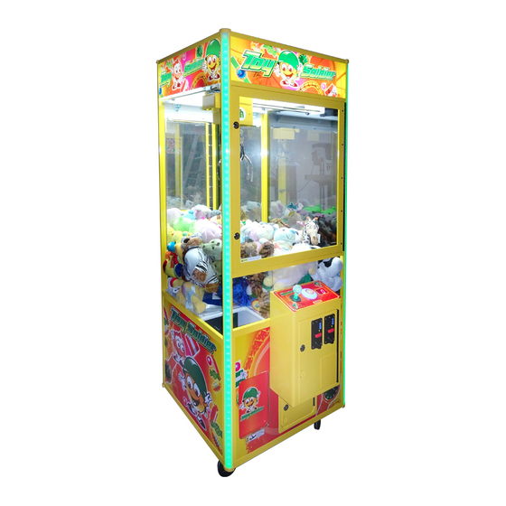
Coastal Amusements TOY SOLDIER Bedieningshandleiding - Pagina 10
Blader online of download pdf Bedieningshandleiding voor {categorie_naam} Coastal Amusements TOY SOLDIER. Coastal Amusements TOY SOLDIER 16 pagina's.
Ook voor Coastal Amusements TOY SOLDIER: Bedieningshandleiding (16 pagina's)

TESTING INSTRUCTION
1. Systems testing:
Adjust COIN1 & COIN2 to N.C. then power on, the display will show [CC]. Adjust DIP SW2 to proceed
with the testing in each item (function). Press【DESCEND】button to scroll thru each item, but make sure
that all switches are properly adjusted per your requirement.(a special purpose for QC Engineer)
DIP SW2
1
Display
2
DIP SW
3
-
4
3567
5
API8001
6
8910
7
Clear record
8
Enter set up value
2. Claws strength:
Adjust COIN1 to N.C. then power on. Displays will show [C0].
Joystick operation
Pull joystick to【Back】
Pull joystick to【Right】
Pull joystick to【Front】
3. Gantry:
Adjust COIN2 to N.C. /or press switch【TEST】then power on. Displays will show〔a0〕.
Joystick/Button operation
【Back】
【Front】
【Descend】+【Right】
【Descend】+【Left】
【Descend】+【Back】
【Descend】+【Front】
4. Error code description:
Error code
E0
E1
Description
Check strongest power of claws
Description
CPU Bit breakdown
Stop-up SW breakdown
: b row, ..., 7
ST
ND
1. 1
: a row, 2
2. ON : Light, OFF : Dark.
3. DIP SW1 shown in Display 1.
4. DIP SW2 shown in Display 2.
Press any buttons to switch around songs.
Press any buttons to switch around voice sound.
Press any buttons to switch around music sound.
1. Displays show〔CL〕.
2. Clear all record back to 0 then re-enter set up value into the
memory chip.
1. Displays blink〔Ld〕.
2. Set up value is saved when displays stop blinking.
Testing items
VR1
VR2
Case
Claws lower down
Claws rises up
Motor moves to right
Motor moves to left
Motor moves backward
Motor moves forward
Error code
E6
E9
Ee
- 9 -
Notes
TH
TH
: g row, 8
: blink.
Displays showing
C1
C2
C3
Displays showing
Description
Flap door motor and/or
control board breakdown
Counter meter not properly
connected
Output sensor breakdown
a3
a4
b1
b2
b3
b4
