Coates ST Series Installatie- en bedieningshandleiding - Pagina 2
Blader online of download pdf Installatie- en bedieningshandleiding voor {categorie_naam} Coates ST Series. Coates ST Series 8 pagina's. 5.5 & 11kw 240v single phase spa heater
Ook voor Coates ST Series: Installatie-, Bedienings- en Onderhoudshandleiding (8 pagina's)
1.0 DESCRIPTION
Coates Spa Heaters are intended for use on spas or
hot tubs having a forced water circulation system.
The water flow through the heater should be at least
15 GPM but should not exceed 80 GPM. Higher
flow may damage the heater. An external bypass
should be installed to limit the flow to within this
range.
2.0 INSTALLATION
WARNING
Only qualified personnel, as defined by National
Electric Code Article 100, should install and
maintain this equipment. Unauthorized alteration
or improper maintenance of this unit may release
the manufacturer from any warranty claims. The
installation must be in accordance with the
instructions in this manual and applicable local
plumbing and electrical codes.
CHECK ELECTRICAL CONNECTIONS TO ALL
COMPONENTS within the heater for tightness.
These can become loose during shipment and
handling.
2.1 PHYSICAL PLACEMENT
The Coates Spa Heater is suitable for indoor or
outdoor installation.
connections and Figures 3A or 3B for electrical
connections.
The heater should be securely
mounted to a smooth, flat surface.
conveniently located next to the filtration equipment.
Leave minimum clearances of 9 inches on the
left for element removal, 12 inches on the front
for maintenance, 6 inches on the back for
service entrance and the right side will be
determined by the plumbing configuration used.
** NOTICE **
NO PRESSURE RELIEF
VALVE IS SHIPPED WITH
THIS HEATER AND NONE
IS REQUIRED PER UL
STD 1261. DO NOT
INSTALL SHUT OFF
VALVE BETWEEN THE
HEATER AND POOL OR
SPA. A CHECK VALVE IS
ACCEPTABLE AND IN
ACCORDANCE TO UL STD
1261 REVISED JULY 1983.
See Figure 1 for piping
It may be
CAUTION
DO NOT INSTALL ANY SHUT-OFF
VALVE ON DISCHARGE SIDE OF
HEATER. A SWING CHECK
VALVE IS PERMITTED.
Exception: If a 30 psi (2.1 Kg/cm
pressure relief valve is installed
between the heater and valve , the
valve may be of the shut-off (ball or
gate) type.
COATES POOL
HEATER
FIGURE 1 – PIPING DIAGRAM
2.2 ELECTRICAL INSTALLATION
THE ELECTRICAL INSTALLATION MUST BE IN
ACCORDANCE WITH ARTICLE 680 OF THE
NATIONAL ELECTRICAL CODE (NEC).
The electrical supply power must be single phase,
2 wire, 240 VAC. The supply must be protected
by a ground fault circuit interrupter (GFCI) in
accordance with NEC Article 680. An electrical
disconnect with over-current protection must be
provided. An insulated ground conductor must be
provided. See Figures 3A or 3B and Table 1 for
supply wire and circuit sizing.
provided for attachment of the BONDING wire per
the NEC Article 680-22, (a)(4). This lug is located
between the inlet and outlet pipes of the heater
1
9
8
7
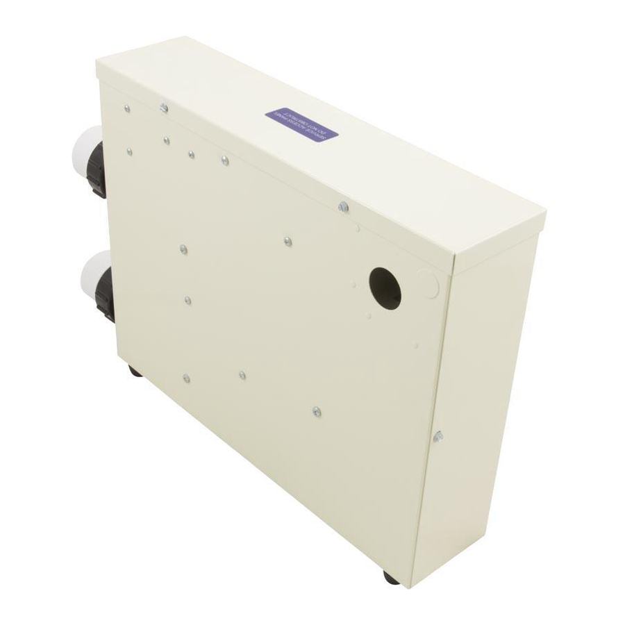
Figure 2 – Coates Spa Heater Assembly.
Refer to Table 2 for part description.
2
)
CHECK
VALVE
FILTER
DRAIN
BALL OR GATE
VALVE
VALVE
CAUTION
A lug has been
2
TEMPERATURE CONTROL
3
C°
40°
25°
100°
35°
30°
ELEM. FLOW
90°
4
6
1
NOTE: TEMP
10
CONTROL BULB
ON LOWER LEG;
TEMP LIMIT BULB
5
ON UPPER LEG
RESET BUTTON
Coates Spa Heater Assembly
POOL
or
SPA
PUMP
BALL OR GATE
VALVE
F°
70°
80°
INLET/OUTLET PVC UNIONS
ID ACCEPTS 1 1/2 PVC PIPE
OD ACCEPTS 2" PVC FITTINGS
CSTILL1B