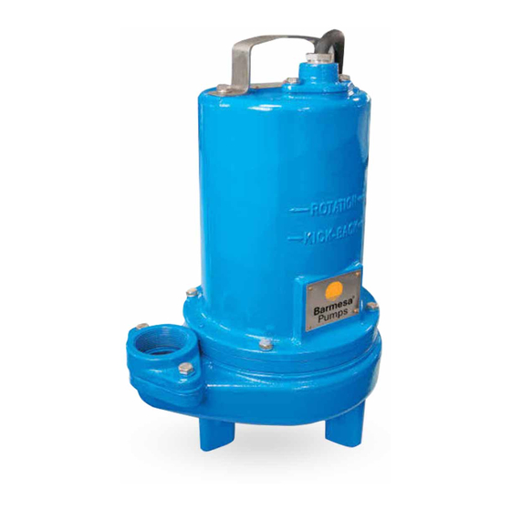
Barmesa Pumps 2BSE51SS Installatie-, bedienings- en onderhoudshandleiding - Pagina 7
Blader online of download pdf Installatie-, bedienings- en onderhoudshandleiding voor {categorie_naam} Barmesa Pumps 2BSE51SS. Barmesa Pumps 2BSE51SS 13 pagina's. Submersible solids handling pumps
Ook voor Barmesa Pumps 2BSE51SS: Installatie-, bedienings- en onderhoudshandleiding (13 pagina's)

Shaft Seal:
14. Lift motor rotor, shaft, bearing (6),
rotating member of seal, washer (7)
from seal plate (15). See Figure 3.
15. Remove seal parts from shaft.
Examine all seal parts, if seal faces
show signs of wear, uneven wear
pattern, chips or scratches replace
entire seal. DO NOT interchange
seal
components,
entire shaft seal (24). If replacing
seal, remove stationary from seal
plate (15) by prying out with flat
screwdriver.
4Reassembly
IMPORTANT! - All parts
must
be
reassembly. Handle seal
parts with extreme care. DO NOT
damage lapped surfaces.
barmesa.com
Shaft Seal:
1. To reassemble, clean seal cavity in
seal plate (15) and oil.
2. Press seal's stationary member
firmly into seal plate (15), use a seal
tool or pipe. Nothing should come in
contact with the seal face except the
seal tool. Be sure the stationary is in
straight.
3. Press lower bearing (6) onto shaft.
4. Place seal's (24) retaining ring and
spring onto shaft. Lightly oil (Do not
use grease) shaft and inner surface
of bellows.
5. With lapped surface of rotating
member facing outward, slide over
shaft using a seal tool, being carefull
not to damage seal face. Make sure
spring is seated in retaining ring and
spring is lined up on rotating
replace
the
member and not cocked or resting
on bellows tail.
Bearing and Motor:
6. Slide rotor/shaft with bearing (6)
and seal parts (24) into seal plate (15)
until bearing seats into seal plate.
Place stator over rotor, lining up
clean
before
motor bolts with holes in seal plate
(15). Insert motor bolts and torque to
17 inch pounds.
7. Lubricate and place square ring (14)
into bore on seal plate (15).
8. On Single phase units, connect
capacitor (4) to motor wires. See
Figure 5. Install ground wire on end
bell if removed. Place fiberglass sleeve
over motor and ground leads if
removed. Pull wires through opening
in top of motor housing while
lowering motor housing onto seal
plate (15).
15
6
9. Place socket head screws (31)
through seal plate into motor housing
and torque to 60 inch pounds.
Impeller and Volute:
10. Install v-gasket (23) and impeller
washer (17) over shaft, and into seal
plate (15).
11. Install impeller (16) by cleaning
the threads with thread locking
compound cleaner. Apply removable
Loctite® 609 or equivalent to shaft
threads. Screw impeller onto shaft
hand tight while using a screwdriver
in the slot at the end of the shaft to
hold it stationary. Rotate impeller to
check for binding.
12. Place gasket (19) onto volute (18).
13. Lower motor housing and seal
plate assembly onto volute (18). Apply
thread
locking
compound
capscrews and with washers place
through motor housing, into volute
and torque to 11 ft. lbs.
Cable Assembly:
14. Check power cord (1) for cracks or
damage and replace if required. Insert
one friction ring, grommet, one
friction ring, and gland nut into motor
housing (3) or conduit box and cable
assembly (1) and torque wire nut to
15 ft. lbs.
23
Service
to
06
