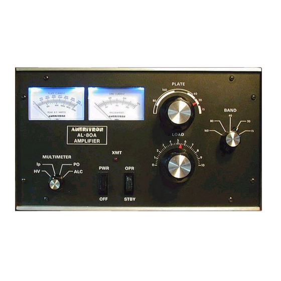
AMERITRON AL-80A Gebruiksaanwijzing - Pagina 4
Blader online of download pdf Gebruiksaanwijzing voor {categorie_naam} AMERITRON AL-80A. AMERITRON AL-80A 6 pagina's. High power linear amplifier
Ook voor AMERITRON AL-80A: Gebruiksaanwijzing (13 pagina's), Gebruiksaanwijzing (7 pagina's), Gebruiksaanwijzing (12 pagina's)

-,
MUL TIMETER
GRID
METER
PLATE
AMI!:.."...
AL-80A
AMPLIFIER
BAND
40
PLATE CURRENT
00
;ggo
,'5"0"0 ,'0"0"0 2~g::
.n~
\'00. :~\uW-LwLu.ut;~
,"?OZ
~o,,~,~tgg"
GRID CURRENT
MULTIMETER
XMT
0
LOAD
4
5
6
3
,\1111111/,
7
\"
11/
2
"
II
8
~'
I~
1~
~9
-
-
I
J
IP,
,PO
HV~
\
/
/ALC
0
PWR
OPR
0":
:"10
'1
II
OFF
.1.
pOWER
SWITCH
STBY
-I-
OPERATE-
STANDBY
SWITCH
TUNING INSTRUCTIONS
Follow the instructions in numerical order. If the various meter readings are different than indicated in the instructions,
check the connections from the exciter to the amplifier and make sure they are correct. Consult the manual for the
exciter if necessary.
1. Set the AL-80A front panel switches as follows:
PWR
-
OFF to OFF
OPR - STBY to STBY
MULTIMETER to HV
2. Plug the A.C. line cord into the proper voltage outlet. The AL-80A is factory wired for 117VAC 50/60 Hz operation.
3. Set the PWR-OFF switch to PWR. The meter lamps should light and the blower should start. Read the 0-3500V
scale on the multimeter. It should indicate 3100 volts nominal.
4. With the amplifier still on standby, tune the exciter into the normal 50 ohm load according to the manufacturer's
instructions. Turn the exciter drive fully down after tuning.
5. Place the bandswitch on the same band as the exciter, the PLATE tuning control in the dial range for the band
selected and the LOAD control at the recommended point for the band in use.
6. With the exciter drive still at zero, place the MULTIMETER switch in the Ip position. Observe the 0-700 mA scale.
It should read zero. Place the STBY-OPR switch in the OPR position.
3
~
