DoorHan PCB-SW 24 Handleiding programmeerinstructies - Pagina 12
Blader online of download pdf Handleiding programmeerinstructies voor {categorie_naam} DoorHan PCB-SW 24. DoorHan PCB-SW 24 20 pagina's.

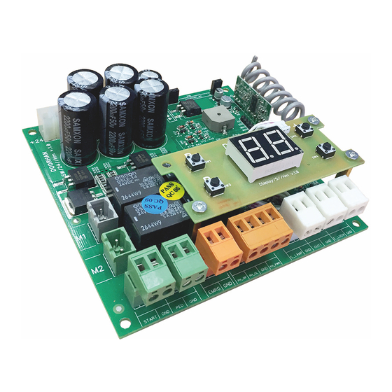
1.2. CONTROL UNIT TERMINALS
WARNING!
If no safety devices are connected to EMRG, PH_OP, PH_CL terminals, then jumper these terminals with COM contact.
Type
Colour
Control board
White
power supply
Motor power
Grey
supply
Control
Green
devices
Safety devices
Orange
Yellow
Accessories
White
Antenna
Green
Transformer
Red
connection
12
Terminal
Connector
#
Name
1
+24
X1
2
GND
1
+24
X2
2
GND
1
X3
M1
2
1
X4
M2
2
1
START
X5
2
GND
1
PED
X6
2
GND
1
EMRG
X7
2
GND
1
PH_OP
2
PH_CL
X8
3
GND
4
PH_PWR Photocell power supply
1
S_LAMP
X9
2
GND
1
OUT_1
X10
2
GND
1
E_LOCK
X11
2
GND
1
GND
X12
2
ANT
1
—
Х17
1
—
1
PE (1)
Х18
2
L (2)
3
N (3)
Connection of power supply from the operator to the board, 24V DC
Connection of autonomous power supply, 24 VDC
Connection of 1st electric motor. Can be used to automate a wicket door or single-
leaf door
Connection of 2nd electric motor. Can not be used to automate a wicket door or
single-leaf door
Connection of circuit closers (NO). Closing of these terminals generates START
command (see section 2.1). When using several devices connect their NO contacts
in parallel
Connection of circuit closers (NO). Closing of these terminals generates PEDES-
TRIAN command (see section 2.1). When using several devices connect their NO
contacts in parallel
Connection of normally closed (NC) devices. Opening of these terminals constantly
generates STOP command (see section 2.1). When using several devices connect
their NC contacts in series
Connection of normally closed (NC) photocells for opening. Response of the de-
vices during door opening results in emergency stop of the door
Connection of normally closed (NC) photocells for closing. Response of the devices
during door closing results in emergency stop and reverse movement of the door
Common terminal for photocells
Signal lamp connection 24 VDC
Universal output OUT1 24 VDC. Operation logic see table 3.3; connection see sec-
tion 1.3
Electric lock connection, see section 1.3
Connection of external antenna of the remote control receiver
Connection of power supply for 230 V step-down transformer
Connection of 230 V power supply to control board input
ELECTRICAL CONNECTIONS
Table 1.1 Electrical сonnections
Device connection
