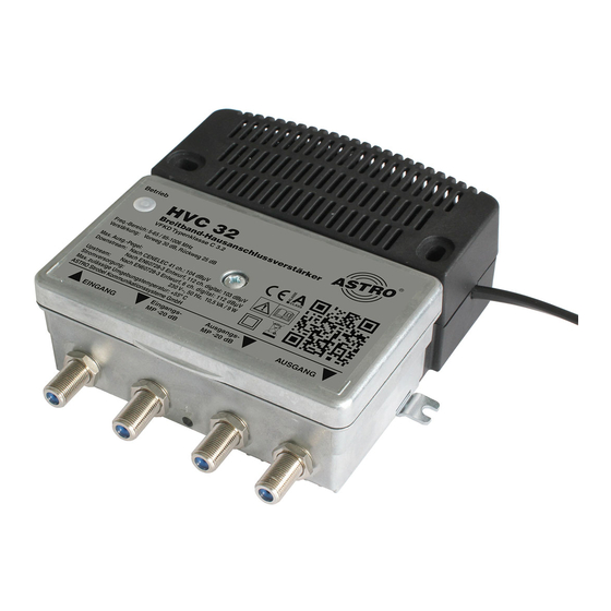
ASTRO HVC 32 Bedieningshandleiding - Pagina 15
Blader online of download pdf Bedieningshandleiding voor {categorie_naam} ASTRO HVC 32. ASTRO HVC 32 20 pagina's. Broadband amplifiers

Configuration
2
1
4
3
6
Operating manual HVC 32 a. HVC 42 -
First configure the amplifier for the transmission of forward signals:
T
ASK
1.
Remove the housing cover by loosening the cover
screw.
2.
When the devices are delivered, the HVB 32, HVB 31 and HVB
42 amplifiers have an attenuator (0...15 dB) [1] and a tilt equal-
iser (0...15 dB) [2] (see left) in the input, which are screwed in.
They can be used to set the desired attenuation and equalisa-
tion. (Input and output are protected against overvoltage.)
3.
You can set an attenuation (0 or 6 dB) between the amplifier
stages by reinserting the jumper [3] accordingly. Observe the
labelling.
4.
You can also set a pre-equalisation of 0 or 7 dB between the
amplifier stages by inserting the
jumper [4] accordingly.
ATTENTION
be exceeded! (maximum input level = output level minus the
set gain for 1006 MHz)
R
:
ESULT
The device is now configured for the transmission of forward sig-
nals.
To transmit return signals, the amplifier must be configured accord-
ingly.
The following describes how to configure the amplifier for the trans-
mission of return signals:
T
ASK
1.
When the device is delivered, the attenuator (0...15 dB) [5] is
5
screwed in and must be set according to the cable network
specifications.
2.
When the device is delivered, the tilt equaliser in the return
path [6] is screwed in (see picture left) and must be set
according to the required cable pre-equalisation or post-equal-
isation.
R
:
ESULT
The device is now configured for the transmission of return signals.
Version 01-2021A
:
The maximum operating level must not
page 15
