Akytec MV110-16DN Gebruikershandleiding - Pagina 3
Blader online of download pdf Gebruikershandleiding voor {categorie_naam} Akytec MV110-16DN. Akytec MV110-16DN 19 pagina's. Analog input module, 16 channel

Description
1. Description
1.1
Function
Digital input module MV110-16DN is an expansion module with 16 digital inputs.
The module has the following functions:
–
Connecting peripheral devices with digital outputs
–
Interpretation of digital signals
–
Pulse counter (see 1.2)
–
RS485 network state diagnostics
–
Generating corresponding fault and alarm signals
–
Slave in Modbus network
The module supports Modbus RTU, Modbus ASCII protocols with automatic protocol
identification.
The module is to be configured using 'M110 Configurator' software via RS485-USB inter-
face adapter IC4 (not included). The latest version of the configuration software is availa-
ble for download on www.akytec.de.
1.2
Counter function
The module also has the ability to use all of its inputs as fast 16 bit counters with a count-
ing frequency of up to 1 kHz. The minimum pulse width is limited to 0.5 ms. Pulses of
higher frequency or of shorter duration are ignored. The counter is responsive to any
rising edges.
When switching off power, the actual count state remains retained in permanent memory.
The counter is set to 0, if it has been reached an overflow, and counting continues.
The module has a debouncing function. This function can be activated for each input by
setting tin.c (debouncing filter) to "On" when making configuration of device parameters
(see Table 5.1). The function is recommended at signal frequencies up to 90 Hz and if
the duty cycle is 50% and more.
1.3
RS485 network
I/O modules of Mx110 series use common standard RS485 for data exchange. RS485
serial interface is based on two-wire technology and half-duplex mode. Protocols Modbus
RTU, Modbus ASCII and akYtec are supported. The network consists of a master device
and can contain up to 32 slave devices. The maximum length is 1200 m. The number of
slave devices and the network length can be increased using a RS485 interface repeater.
Devices are connected to a network according to linear (bus) topology. It means that the
line goes from the first device to the second one, from the second one to the third one,
etc. Star connections and spur lines are not allowed.
Line reflections always occur at the open bus ends (the first and the last node). The high-
er the data transmission rate, the stronger they are. A terminating resistor is needed to
minimize reflections. Experience proves that the most efficient practice is to use terminat-
ing resistors of 150 ohm.
The module can be used as slave devices only. Master device can be PLC, PC with
SCADA software or control panel.
1.4
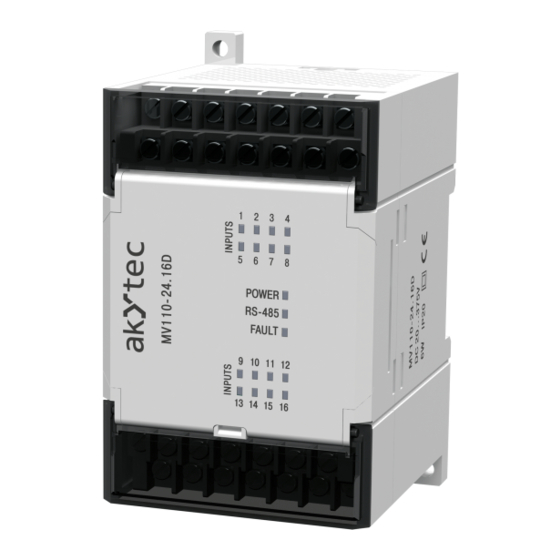
Construction
─
Enclosure:
─
Terminal strips:
LED „POWER":
─
LED „RS-485":
─
LED „FAULT":
─
ken
16 LEDs „INPUTS": light up, when at relative input is 1
─
akYtec GmbH · Vahrenwalder Str. 269 A · 30179 Hannover · Germany · Tel.: +49 (0) 511 16 59 672-0 · www.akytec.de
Plastic, grey, for wall and DIN rail mounting
2 extractable terminal strips with 20 screw terminals each
power supply
blinks when exchanging data at serial port
lights up when the data exchange process on serial port is bro-
2
