Baumer HUBNER HDmag MHGE 400 Montage- en bedieningsinstructies - Pagina 14
Blader online of download pdf Montage- en bedieningsinstructies voor {categorie_naam} Baumer HUBNER HDmag MHGE 400. Baumer HUBNER HDmag MHGE 400 32 pagina's. Encoder with bearings-incremental
4
Montage / Mounting
4.2
Montage des Abtastkopfes
Typenschild
Type label
* Siehe Seite 7 oder 8
See page 7 or 8
Unbedingt auf einen Luftspalt von
nominell 1
und Abtastkopf achten. Bei Montage
auf Bündigkeit zwischen dem Geber-
rad und dem Abtastkopf achten (max.
zulässiger Axialversatz während des
Betriebes: ±3 mm).
11
3.8
3
mm zwischen Geberrad
+1.2
-0.9
4.2
Mounting the sensor head
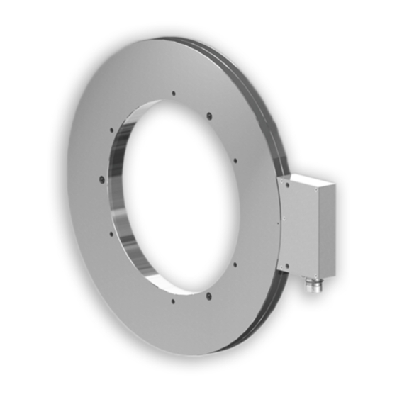
Geberrad
Encoder wheel
Befestigungsmöglichkeit für den Abtastkopf (Beispiel).
Fixing element for the sensor head (example).
*
*
0
Baumer_MHGE400_II_DE-EN (19A3)
*
3.8
Zul. Anzugsmoment:
Max. tightening torque:
M
t
3.1 *
*
3.9
Zulässiger Axialversatz zwischen
Abtastkopf und Geberrad
Permissible axial displacement
between the sensor head and the
encoder wheel
Make sure there is an 1
nally air gap between the encoder
wheel and the sensor head. Check the
flush alignment of the encoder wheel
and the sensor head on mounting
(max. permissible axial displacement
during operation: ±3 mm).
= 8...10 Nm
6 mm
0
0
±3 mm
mm nomi-
+1.2
-0.9
MB202 - 11069322