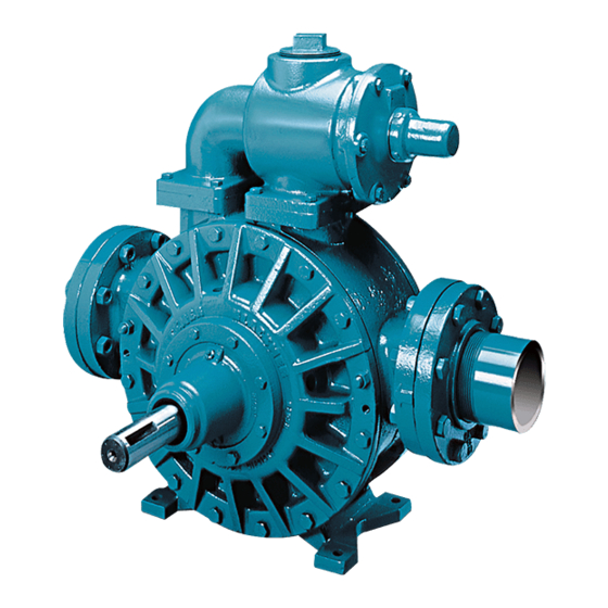
Dover PSG BLACKMER MLXW4B Instructies voor installatie, bediening en onderhoud - Pagina 15
Blader online of download pdf Instructies voor installatie, bediening en onderhoud voor {categorie_naam} Dover PSG BLACKMER MLXW4B. Dover PSG BLACKMER MLXW4B 20 pagina's. Power pumps

MAINTENANCE: MLN4B, MRLN4B
7.
Follow Steps 2 through 5 to install the remaining head
and hub assemblies. Remember to grease the casing
chamfer and the three head chamfers.
8.
PACKING AND PACKING FOLLOWER
When necessary to repack, use a full set of new
packing rings (19). Packing is furnished in sets with the
correct number of rings. Never add new rings to an old
set of packing.
a. Insert the packing washer (58) into the stuffing box
of the inboard hub (20C).
b. Insert each packing ring (19) separately into the
stuffing box, using the packing follower (75) to
properly seat each ring after placement. Be sure to
stagger the split joints approximately 180 degrees
apart so that they are not overlapping or near the
joint of the preceding ring.
c. After the packing rings are in place, install and
tighten the two packing follower removal nuts (18A)
against the hub (20C).
d. Place the packing follower (75) snugly against the
packing (19). Install the two packing follower stud
nuts (18) and tighten lightly.
Failure to stop the pump before
adjusting the shaft packing can cause
severe personal injury.
Hazardous
machinery can
cause serious
personal injury.
9. PACKING ADJUSTMENT – Packing must be properly
adjusted to prevent overheating.
a. While the liquid is being pumped, check for leakage
from the stuffing box. STOP the pump and uniformly
tighten the packing follower stud nuts (18) 1/4 turn at
a time to reduce leakage.
b. Restart the pump and check the stuffing box
temperature several minutes after each adjustment
for signs of overheating.
c. Check the packing (19) again after 20-30 minutes of
running the pump, and readjust if necessary.
NOTE: Some leakage is desirable to lubricate the
packing, but in some cases is unacceptable, depending
on the application.
10. BLACKMER TRIPLE-LIP SEAL (if equipped)
On pumps equipped with a Blackmer triple-lip seal, refer
to the separate literature accompanying the triple-lip
seal for installation instructions.
11. COMMERCIAL MECHANICAL SEAL (if equipped
On pumps equipped with a commercial mechanical
seal, refer to the separate literature accompanying the
mechanical seal for installation instructions.
12. RELIEF VALVE ASSEMBLY (if equipped)
a. Insert the valve (9) into the relief valve body (6) with the
fluted end inward.
b. Install the relief valve spring (8), spring guide (7) and
guide rod (45) against the valve.
c. Attach a new relief valve gasket (10) and the valve
cover (4) on the cylinder.
d. Screw the relief valve adjusting screw (2) into the valve
cover until it makes contact with the spring guide (7).
e. Install the relief valve cap (1) and gasket (88) after the
relief valve has been precisely adjusted.
The relief valve setting MUST be tested and adjusted
more precisely before putting the pump into service.
Refer to "Relief Valve Setting and Adjustment"
13. Reinstall coupling, shaft key (35), and coupling guards.
14. SHAFT COVER
a. Install the shaft cover O-ring (26) in the groove in the
shaft cover.
b. Lubricate the chamfer on the outboard hub, and slide
the shaft cover (27) over the shaft against the hub.
c. Install and tighten the two shaft cover capscrews (28).
Do not operate
without guard in
place.
15. Refer to "Pre-Start Up Check List" and "Start Up
Procedures" sections of this manual prior to pump
operation.
106-A00
Page 15/20
NOTICE:
Operation without guards in place can
cause serious personal injury, major
property damage, or death.
