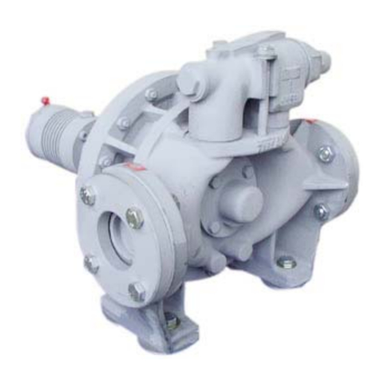
Dover PSG Mouvex AF HT Installatie, bediening en onderhoud - Pagina 4
Blader online of download pdf Installatie, bediening en onderhoud voor {categorie_naam} Dover PSG Mouvex AF HT. Dover PSG Mouvex AF HT 18 pagina's. Construction o

2.1 Choice of pump
To obtain the service expected from a MOUVEX pump,
regarding both performance and longevity, it is vital that
the type of pump, its speed and the materials used for its
construction are determined as a function of the pump
output, its installation and operating conditions.
You can contact our Technical Services at any time to
ask for the information you require.
2.2 Piping diameters
The location of the pump in the transfer or recycling circuit
should always be determined so as to reduce the suction
height and length of the piping as much as possible.
The diameter of the pipes must be determined as a func-
tion of their length on the one hand, and the flow and vis-
cosity of the product on the other, so that head loss
remains within design limits. Therefore it is difficult to
give general and precise directions.
However, we recall that it is never prejudicial to plan for
wide piping diameters, particularly regarding the intake.
For the discharge, it is also possible to plan for a diame-
ter equal to that of the pump's orifices, and on the inta-
ke, for a wider diameter if suction is very strong. In the
case of viscous products, the determination of this dia-
meter is very important since the variation of head loss
is proportional to the viscosity and inversely proportional
to the power of 4th of the diameter. Therefore a small
reduction of piping diameter can have major consequen-
ces. Our Technical Services are always available to pro-
vide you with precise data if you give them accurate
information or, better still, the installation plans.
2.3 Piping assembly
WARNING
FAILURE TO RELIEVE THE SYSTEM
PRESSURE PRIOR TO PERFORMING
ANY WORK ON THE PUMP OR THE
INSTALLATION CAN CAUSE PERSONAL
INJURY OR PROPERTY DAMAGE.
Hazardous pressure
can cause
personal injury
or property damage.
Wherever possible, siphons and reverse slopes in the
suction piping must be avoided and all the gaskets must
be installed with great care to avoid air from entering the
piping.
The elbows must always have a large radius and must
not be assembled too close to the pump flanges, at the
inlet as well as the outlet side.
A straight pipe 5 diameters is recommended between
the pump flange and any pipe fitting (elbow, valve...).
The stresses exerted by the piping on the pump can
deform the pump parts, increase wear, misalign the bea-
rings and even cause parts to break.
NT 1003-D00 09.12 AF HT e
2. INSTALLATION
2.4 Direction of rotation
Hazardous pressure
personal injury
or property damage.
4/18
The pipes must be designed to allow thermal expansion
and contraction and be firmly secured (the use of flexi-
ble hoses and expansion loops is recommended).
We recommend placing isolating valves close to the
pump flanges to permit dismantling and replacement
without having to drain the installation. These valves
should have the same diameter as the pipes and, by
preference, be a full bore model.
A strainer should be fitted in the suction line to prevent
the introduction of foreign bodies into the pump.
Before installing the new piping and tanks, clean them
carefully to remove welding waste, rust, etc., which
when carried by the liquid may damage the pump.
If the liquid may freeze or solidify, prepare for draining
the piping by installing drain taps at the low points and
air vents at the high points.
In the case of a very high intake or if you wish to prevent
the piping from emptying at shutdown, you can install a
foot valve. It should have a large diameter so as not to
generate additional head loss.
WARNING
FAILURE TO RELIEVE THE SYSTEM
PRESSURE PRIOR TO PERFORMING
ANY WORK ON THE PUMP OR THE
INSTALLATION CAN CAUSE PERSONAL
INJURY OR PROPERTY DAMAGE.
can cause
The MOUVEX pump is reversible; this allows it to always
circulate the liquid in the desired direction by choosing
the corresponding direction of rotation.
The intake and discharge sides are determined as fol-
lows :
When an observer faces the shaft, if rotation takes place
clockwise, the intake is on the left; on the contrary if the
rotation is anticlockwise, the intake is on the right.
Suction
Figure A - Clockwise rotation
Discharge
