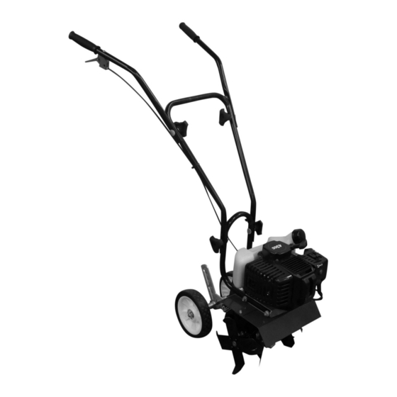
DR Power Equipment PILOT 2C Veiligheids- en bedieningshandleiding - Pagina 15
Blader online of download pdf Veiligheids- en bedieningshandleiding voor {categorie_naam} DR Power Equipment PILOT 2C. DR Power Equipment PILOT 2C 20 pagina's. 2-cycle tiller cultivator

Replacing Wheels
Tools Recommended:
Two 14mm Wrenches
1. Hold the Axle Bolt securing the left side Wheel using a 14mm Wrench and
remove the Locknut and Washer on the right side using a 14mm Wrench
(Figure 15).
2. Tilt the machine to the left side to remove the right side Wheel. Tilt the
machine to the right side to remove the Axle Bolt, Washer, and left side
Wheel.
Note: Ensure the Spring and Washer are in position on the Wheel Shaft when
installing the left side Wheel and Axle Bolt. The Washer must be positioned
between the Spring and Wheel. On page 18, see explode drawing items 47
and 48 for reference to position the Spring and Washer correctly.
3. Install the new Wheels in the reverse order and tighten the Axle Bolt and
Locknut.
Tine Remove and Replace
Tools and Supplies Recommended:
Two 13mm Wrenches
Note: For ease of disassembly and assembly, block up the machine so that the Tines
are off the ground.
Tine Removal:
1. Remove the Bolt and Locknut that secures the right side Tine Assembly to
the Shaft using two 13mm Wrenches (Figure 16).
2. Remove the Bolt and Locknut that secures the left side Tine Assembly to the
Shaft using two 13mm Wrenches.
3. Slide the Tine Assemblies off the Shaft.
Tine Installation:
1. Install the left side Tine Assembly onto the Shaft with the squared edge
facing forward the angled Tine edge facing back (Figure 17).
2. Align the holes of the left side Tine Assembly with the Shafts and secure it
with the Bolt and Locknut using two 12mm Wrenches.
3. Install the right side Tine Assembly onto the Shaft with the squared Tine
edge facing forward the angled Tine edge facing back.
4. Align the holes of the right side Tine Assembly with the Shafts and secure it
with the Bolt and Locknut using two 12mm Wrenches.
Note: It is important the Tine Assemblies are installed on the correct right and left
sides to work properly. The square Tine edges face forward and the angled
Tine edges face back.
Axle Bolt
with Washer
Figure 15
Bolt and
Right Hand Tine
Locknut
Assembly
Figure 16
Square
Edge
Figure 17
CONTACT US AT www.DRpower.com
Right Side Wheel
with Locknut and
Washer
Left Side
Wheel
Left Hand Tine
Assembly
Angled
Edge
15
