AMS AS5600 Bedieningshandleiding - Pagina 4
Blader online of download pdf Bedieningshandleiding voor {categorie_naam} AMS AS5600. AMS AS5600 10 pagina's. 12-bit programmable contactless potentiometer
Ook voor AMS AS5600: Bedieningshandleiding (12 pagina's), Handmatig (14 pagina's), Gebruikershandleiding (13 pagina's)

AS5600-SO_EK_AB
Operation Manual
Header
J2
J2
J2
J2
J3
J3
J3
J3
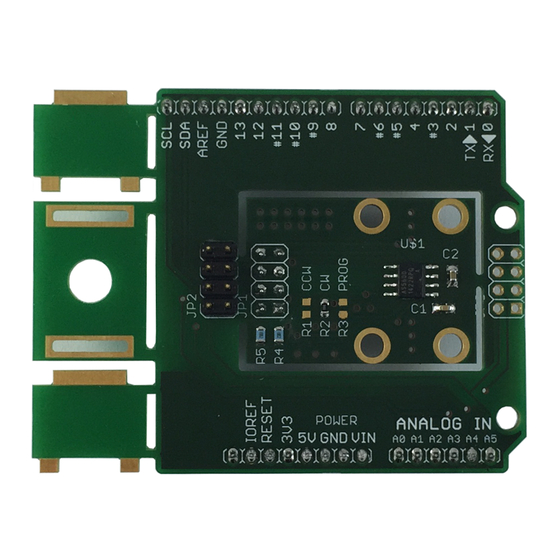
2.2 Adapter Board Description
The AS5600 is connected over the dual-row 2.54mm 4-pin header footprint. Connect the desired
pins of the AS5600 using the headers and resistors.
Figure 1:
Adapterboard Description
I2C pull-up
resistors
Short J1 to
operate in
3.3V mode
Use 0R for R3
to enable
PGO mode
www.ams.com
Arrow.com.
Arrow.com.
Arrow.com.
Arrow.com.
Downloaded from
Downloaded from
Downloaded from
Downloaded from
Pin
Symbol
Description
1
SCL
I2C Clock
2
SDA
I2C Data
3
GND
Ground
4
VDD
Positive Power
Supply
1
VRG
LDO Pin in 5V
Mode
2
PGO
Programming Mode
3
DIR
Direction input
4
OUT
Output Pin
Info
Use R4 if pull-up is required
Use R5 if pull-up is required
Leave open in 5V mode. Pull to VDD using
J1 in 3.3V Mode
Pull to GND using R3 for Programming
Option B (refer to the datasheet)
CCW default. Pulled to GND using R2.
Remove R2 and insert at R1 for CCW
direction.
Analog Output default, PWM possible, Is
used for programming option B
Revision 1.0 / 05.05.2014
page 4/10
