AMS AS5601 Handmatig - Pagina 3
Blader online of download pdf Handmatig voor {categorie_naam} AMS AS5601. AMS AS5601 13 pagina's. Usb interface & programming box
Ook voor AMS AS5601: Bedieningshandleiding (12 pagina's), Gebruikershandleiding (13 pagina's)

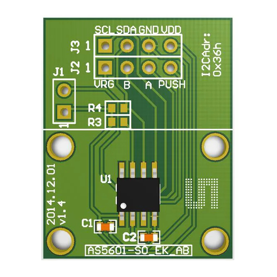
AS5601 Adapter Board
1
Introduction
The adapter board allows an easy and fast evaluation of the AS5601 rotary magnetic position
sensor in the lab or together with an existing system. This small factor board is fully assembled with
AS5601 position sensor and its necessary external components. All relevant signals are available
on a dual-row 2.54mm 4-pin header footprint and can be easily wired to an existing application.
The AS5601 is an easy-to-program magnetic rotary position sensor with incremental quadrature
(A/B) and 12-bit digital outputs. Additionally, the PUSH output indicates fast airgap changes
between the AS5601 and magnet which can be used to implement a contactless pushbutton
function in which the knob can be pressed to move the magnet toward the AS5601.
The I²C interface is used for configuration and user programming of non-volatile parameters in the
AS5601.
2
Kit Content
This kit contains following material listed in
webpage.
Table 1:
Kit Content
No.
Item
1
AS5601-SO_EK_AB
2
AS5000-MD6H-1
3
Getting Started
The AS5601 adapter board is ideal for rapid setup of a contactless encoder knob. Additionally to the
adapter board, a sensor magnet in a mechanical setup is required. A reference magnet comes with
the kit.
3.1 Adapter Board Pin-Out
The pin-out of the adapter board is shown in
refer to the product datasheet.
Table 2:
Adapter Board Pin-Out
Header
Pin
Symbol
J3
1
SCL
J3
2
SDA
J3
3
GND
J3
4
VDD
J2
1
VRG
ams Eval Kit Manual, Confidential
[v1-00] 2014-Jul-31
Table
1. Additional material can be found on our
Description
Reference Magnet
Table
2. For additional information on the AS5601 pins
Description
I2C Clock
I2C Data
Ground
Positive Power
Supply
LDO Pin in 5V
Info
Find the datasheet online at
http://ams.com/eng/AS5000-MD6H-1
Info
Use R3 if pull-up is required
Use R4 if pull-up is required
Leave open in 5V mode. Pull to VDD using
Page 3
Document Feedback
