AIRSLED VM2401 Gebruikershandleiding - Pagina 3
Blader online of download pdf Gebruikershandleiding voor {categorie_naam} AIRSLED VM2401. AIRSLED VM2401 9 pagina's. Vending mover
Ook voor AIRSLED VM2401: Gebruikershandleiding (9 pagina's)

•
If your model has Variable Speed (VS) performance, you will be able to control the rate and height of
air beam inflation for greater control and safety in tight, overhead clearance situations.
* IMPORTANT Vending Mover air beams are 12" W x 39" L and are recommended for loads up to 35" deep. If the
load's depth is greater than 35", Airsled's Side Access air beams which are 10" W x 48" L are recommended.
POSITIONING THE AIR BEAMS
•
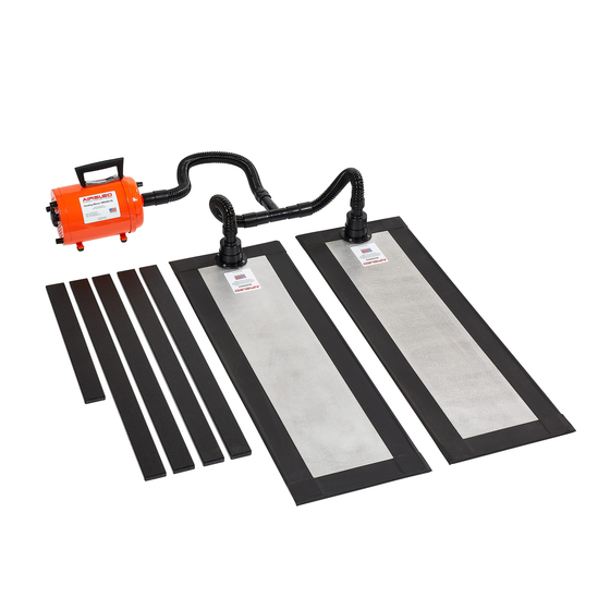
Vending Mover air beams are 3/16" thick. There must be enough clearance between the floor and the
load's base to allow the air beams to be freely slid into place. DO NOT force the air beams under the
load.
•
If the gap between the air beam and load's base is greater than 1 ½", the air beams may not produce
the necessary lift. The included spacer sticks are ½" thick and may adequately bridge the gap. For
larger gaps, Airsled offers ADJUSTABLE SPACER SYSTEMS. More information on these items can
be found on www.Airsled.com. Wood blocking can also be used to bridge the gap.
•
Slide the air beams under the load. See figure 1.
•
Placement of the air beams will generally be done either through front or side access. See figure 2 &
3. Optimal Airsled performance will be achieved by centering the air beams under the load so that the
same length of air beam extends from the front as well as the back. Pushing the air beams as wide
apart as possible is also recommended.
Figure 1
•
Vending Mover model VM24XX with 12" wide x 39" long air beams is recommended for loads whose
base does not exceed 35" deep. If dealing with a load greater than 35" deep or require rotating the
load 90 degrees to pass through a narrow opening, Airsled offers a set of 10" wide x 48" long Side
Access air beams. More information can be found on www.Airsled.com.
CONNECTING THE AIRSLED COMPONENTS
•
No tools are required to connect or disconnect the Airsled components. All connections between the
blower, lead hose, Tee connector, supply hoses and air beam inlets should be done by hand until a
snug fit. See figure 4.
NOTE: When connecting or
disconnecting the supply
hoses to the air beams, do so
by grabbing the:
Solid hose end
Solid plastic inlet
Pulling only the soft hoses
may damage your system.
Figure 2
66 Albe Dr.
Newark, DE 19702
Page 2 of 8
Figure 3
Figure 4
Email:
Phone Number:
1-800-AIRSLED (1-800-247-7533)
